TRENDnet TEW-432BRP User Manual
Hide thumbs
Also See for TEW-432BRP:
- User manual (61 pages) ,
- Quick installation manual (18 pages) ,
- Specifications (2 pages)
Table of Contents
Advertisement
Advertisement
Table of Contents

Related Manuals for TRENDnet TEW-432BRP


Summary of Contents for TRENDnet TEW-432BRP
- Page 2 Regulatory notes and statements Wireless LAN, Health and Authorization for use Radio frequency electromagnetic energy is emitted from Wireless LAN devices. The energy levels of these emissions however are far much less than the electromagnetic energy emissions from wireless devices like for example mobile phones.
-
Page 3: Fcc Interference Statement
FCC Radio Frequency Exposure statement This Wireless LAN radio device has been evaluated under FCC Bulletin OET 65 and found compliant to the requirements as set forth in CFR 47 Sections 2.1091, 2.1093, and 15.247 (b) (4) addressing RF Exposure from radio frequency devices. The radiated output power of this Wireless LAN device is far below the FCC radio frequency exposure limits. -
Page 4: Safety Information
Safety Information Your device contains a low power transmitter. When device is transmitted it sends out radio frequency (RF) signal. CAUTION: To maintain compliance with FCC’s RF exposure guidelines, this equipment should be installed and operated with minimum distance 20cm between the radiator and your body. -
Page 5: Table Of Contents
TABLE OF CONTENT ..................1 BOUT UIDE Purpose ........................................1 Terms/Usage ......................................1 Overview of this User’s Guide .................................. 1 ................... 2 NTRODUCTION Applications: ......................................2 Supported Features: ....................................3 ................4 NPACKING AND ETUP ... - Page 6 Routing ........................................42 Static ........................................42 Dynamic ....................................... 43 Routing Table ...................................... 44 Access ........................................44 Filters ........................................44 Virtual Server ....................................... 50 Special AP ......................................51 DMZ ........................................52 Firewall Rule ......................................
-
Page 7: About This Guide
ABOUT THIS GUIDE Congratulations on your purchase of this IEEE 802.11g Wireless Broadband Router. This integrated access device combines Internet gateway functions with wireless LAN and Fast Ethernet switch. It provides a complete solution for Internet surfing and office resource sharing, and it is easy to configure and operate for every user. Purpose This manual discusses how to install the IEEE 802.11g Wireless Broadband Router. -
Page 8: Introduction
INTRODUCTION With the explosive growth of the Internet, accessing information and services at any time, day or night has become a standard requirement for most people. The era of the standalone PC is waning. Networking technology is moving out of the exclusive domain of corporations and into homes with at least two computers. -
Page 9: Supported Features
Supported Features: High speed data transfer rate NAT for sharing 1 IP address to all LAN/WLAN users. PPPoE and PPTP protocol for Dial-Up ADSL. 64/128 bit WEP Encryption WPA-PSK, WPA2-PSK, WPA, WPA2 security DHCP Server / Client. UPnP (Universal Plug and Play). WMM (Wi-Fi Multimedia Quality of Service) WPS (Wi-Fi Protected Setup) Virtual Server mapping. -
Page 10: Unpacking And Setup
UNPACKING AND SETUP This chapter provides unpacking and setup information for the IEEE 802.11g Wireless Broadband Router. Unpacking Open the box of the WLAN Router and carefully unpack it. The box should contain the following items: One IEEE 802.11g Wireless Router One CD-ROM (User’s Guide) One Multi-Language Quick Installation Guide One 2dBi gain dipole antenna... -
Page 11: Hardware Installation
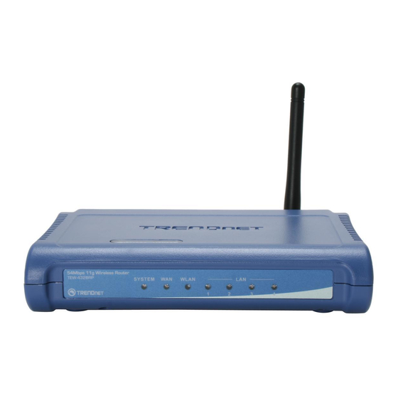
HARDWARE INSTALLATION Front Panel The figure below shows the front panel of the IEEE 802.11g Wireless Router. Front Panel SYSTEM This indicator blinking green means the WLAN Router is working successfully. Otherwise, this indicator always on or off means the function of the WLAN Router has failed. -
Page 12: Rear Panel
Rear Panel The figure below shows the rear panel of the IEEE 802.11g Wireless Router. Rear Panel Antenna There is one 2dBi gain antenna on the rear panel for wireless connection. LAN (1-4) Four RJ-45 10/100Mbps Auto-MDIX ports for connecting to either 10Mbps or 100Mbps Ethernet connections. -
Page 13: Hardware Connections
Hardware connections Connecting the WLAN Router 1. Plug in one end of the network cable to the WAN port of the WLAN Router. 2. Plug in the other end of the network cable to the Ethernet port of the xDSL or Cable modem. -
Page 14: Pc Network Tcp/Ip Setting
PC NETWORK TCP/IP SETTING The network TCP/IP settings differ based on the computer’s operating system (Win95/98/ME/NT/2000/XP/Vista) and are as follows. Windows 95/98/ME 1. Click on the “Network neighborhood” icon found on the desktop. 2. Click the right mouse button and a context menu will be show. 3. -
Page 15: Windows 2000
6. Select “None” for the “Gateway address” field. Windows 2000 Double click on the “My Computer” icon on the desktop. When “My Computer” window opens, open the “Control Panel” and then open the “Network dialup connection” applet. Double click on the “Local area network connection” icon. Select “Properties”... -
Page 16: Windows Xp
Windows XP Point the cursor and click the right button on the “My Network Place” icon. Select “properties” to enter the TCP/IP setting window. 1. Set “IP address” to “Obtain an IP address automatically.” 2. Set “DNS” to “Obtain DNS server address automatically.” Windows Vista Go to Start and select Control Panel, double click on Networking and Sharing center icon. - Page 17 2. Click on Internet Protocol Version 4(TCP/IPv4) option and click on Properties button 3. Set IP address and DNS to obtain information automatically.
-
Page 18: Configuration
Before configuring the WLAN Router through WLAN, make sure that the SSID, Channel and the WEP is set properly. The default setting of the WLAN Router that you will use: SSID: TRENDnet Channel: Auto Security: disable Login to the WLAN Router... -
Page 19: Setup Wizard
Setup Wizard Setup wizard is provided as part of the web configuration utility. User can simply follow the step-by-step process to get the wireless Router configuration ready to run in 5 easy steps by clicking on` the “Wizard” button on the function menu. The following screen will appear. - Page 20 Step 2: Set LAN connection and DHCP server Set user’s IP address and mask. The default IP is 192.168.10.1. If the user chooses to enable DHCP, please click “Enable”. DHCP enabled is able to automatically assign IP addresses. Please assign the range of IP addresses in the fields of “Range start”...
- Page 21 Obtain IP automatically (DHCP client): If the user has enabled DHCP server, choose "Obtain IP automatically (DHCP client)" to have the WLAN Router assign IP addresses automatically.
- Page 22 Fixed IP Address: If the Internet Service Provider (ISP) assigns a fixed IP address, choose this option and enter the assigned WAN IP Address, WAN Subnet Mask, WAN Gateway Address and DNS Server Addresses for the WLAN Router.
- Page 23 PPPoE to obtain IP automatically: If connected to the Internet using a PPPoE (Dial-up xDSL) connection, and the ISP provides a User Name and Password, then choose this option and enter the required information.
- Page 24 PPPoE with a fixed IP address: If connected to the Internet using a PPPoE (Dial-up xDSL) connection, and the ISP provides a User Name, Password and a Fixed IP Address, choose this option and enter the required information.
- Page 25 PPTP: If connected to the Internet using a PPTP xDSL connection, enter your IP, Subnet Mask, Gateway, Server IP, PPTP Account and PPTP Password.
- Page 26 L2TP: If connected to the Internet using a L2TP (Dial-up xDSL) connection and the ISP provides a Server IP, Account and Password information, choose this option and enter the required information.
- Page 27 Big Pond Cable(Australia): If your ISP is Big Pond Cable, the ISP will provide a User Name, Password, Authentication Server and Login Server IP (Optional). Choose this option and enter the required information.
- Page 28 Russian PPPoE: If your ISP is Russian PPPoE, the ISP will provide a User Name, Password, WAN Physical IP Address, WAN Physical Subnet Mask and WAN Physical Gateway IP Address. Choose this option and enter the required information.
- Page 29 Russian PPTP: If connected to the Internet using Russian PPTP xDSL connection, enter your IP, Subnet Mask, Gateway, Server IP, PPTP Account and PPTP Password.
- Page 30 Russian L2TP: If connected to the Internet using Russian L2TP (Dial-up xDSL) connection and the ISP provides a Server IP, Account and Password information, choose this option and enter the required information.
- Page 31 Step 4: Set Wireless LAN connection Click “Enable” to enable Wireless LAN. If user enables the Wireless LAN, type the SSID in the text box and select a communications channel. The SSID and channel must be the same as wireless devices attempting to connect to the WLAN Router. Step 6: Setup completed The Setup wizard is now completed.
-
Page 32: Advanced Configuration
IP address, subnet mask, and domain name. LAN and DHCP profiles are listed in the DHCP table at the bottom of the screen. Host Name: Type the host name in the text box. The host name is required by some ISPs. The default host name is "TRENDnet"... - Page 33 IP Address: This is the IP address of the WLAN Router. The default IP address is 192.168.10.1. Subnet Mask: Type the subnet mask for the WLAN Router in the text box. The default subnet mask is 255.255.255.0. DHCP Server: Enables the DHCP server to allow the WLAN Router to automatically assign IP addresses to devices connecting to the LAN.
-
Page 34: Wan
This screen enables users to set up the WLAN Router WAN connection, specify the IP address for the WAN, add DNS numbers, and enter the MAC address. Connection Type: Select the connection type, either DHCP client, Fixed IP, PPPoE, PPTP, L2TP, BigPond Cable, Russian PPPoE, Russian PPTP or Russian L2TP from the drop-down list. -
Page 35: Password
Password This screen enables users to set administrative and user passwords. These passwords are used to gain access to the WLAN Router interface. Administrator: Type the password the Administrator will use to log into the system. The password must be typed again for confirmation. The Administrator can also authorize users the ability to configure the WLAN Router. -
Page 36: Time
Time This screen enables users to set the time and date for the WLAN Router's real-time clock, select properly time zone, and enable or disable daylight saving. Local Time: Displays the local time and date. Time Zone: Select the time zone from the drop-down list. Synchronize the clock with: Select the clock adjustment method form the drop- down list. -
Page 37: Dynamic Dns
Dynamic DNS This synchronizes the DDNS server with your current Public IP address when you are online. First, you need to register your preferred DNS with the DDNS provider. DDNS: Enable to allow WLAN router to allow DDNS service. Server Address: Select DDNS service on the pull down menu. Host Name: Enter host name of DDNS serve being used. -
Page 38: Wireless
Wireless This section enables users to configuration the wireless communications parameters for the WLAN Router. Basic This page allows user to enable and disable the wireless LAN function, create a SSID, and select the channel for wireless communications. Enable/Disable: Enables or disables wireless LAN via the WLAN Router. SSID: Type an SSID in the text box. -
Page 39: Security
Security This page allows users to set the wireless security of the WLAN router for a secure wireless communication. Authentication Type: The authentication type default is set to open system. There are four options: Disabled, WEP, WPA, WPA2 and WPA-Auto. WEP Encryption WEP: Open System and Shared Key requires the user to set a WEP key to exchange data with other wireless clients that have the same WEP key.. - Page 40 WEP Key: Select the level of encryption from the drop-down list. The WLAN Router supports, 64 and 128-bit encryption. Key 1 ~ Key 4: Enables users to create up to 4 different WEP keys. Manually enter a set of values for each key. Select a key to use by clicking the radio button next to the key.
-
Page 41: Advanced
WPA-PSK/WPA2-PSK Security If WPA, WPA2 or WPA-Auto PSK is selected. Cipher Type: Select the cipher type for TKIP or AES encryption, Selected Auto for auto detects the cipher type. Passphrase: The length should be 8 characters at least. Advanced This screen enables users to configure advanced wireless functions. Beacon Interval: Type the beacon interval in the text box. -
Page 42: Wi-Fi Protected Setup
RTS Threshold: Type the RTS (Request-To-Send) threshold in the text box. This value stabilizes data flow. If data flow is irregular, choose values between 256 and 2346 until data flow is normalized. Fragmentation Threshold: Type the fragmentation threshold in the text box. If packet transfer error rates are high, choose values between 1500 and 2346 until packet transfer rates are minimized. -
Page 43: Status
WPS: Enable or Disable the WPS (Wi-Fi Protected Setup) function Status: Display the state (Un-configured State/Configured State) information of WPS. Self-PIN Number: Display the default PIN number of WLAN Router. Client PIN Number: Type Client PIN number the client uses to negotiate with WLAN Router via WPS protocol and press “Start PIN”. -
Page 44: Log
WAN: This section displays the WAN interface configuration including the MAC address, Connection status, DHCP client status, IP address, Subnet mask, Default gateway, and DNS. Click “DHCP Release” to release the IP addresses assigned to the WLAN router from your ISP. Click “DHCP Renew” to obtain a new IP address from your ISP. Wireless: This section displays the wireless configuration information, including the MAC address, the Connection status, SSID, Channel and Authentication type. -
Page 45: Log Setting
Time: Displays the time and date that the log entry was created. Message: Displays summary information about the log entry. Source: Displays the data source. Destination: Displays the data destination. Note: Displays the IP address of the communication Log Setting This screen enables users to set Router Log parameters. -
Page 46: Statistic
Every day, Every Monday ... - The log is sent on the interval specified. • If "Every day" is selected, the log is sent at the time specified. If the day is specified, the log is sent once per week, on the specified day. Select the time of day you wish the E-mail to be sent. - Page 47 Connected Time: Displays how long the wireless client has been connected to the WLAN Router. MAC Address: Displays the wireless client’s MAC address.
-
Page 48: Routing
Routing This selection enables users to set how the WLAN Router forwards data: Static and Dynamic. Routing Table enables users to view the information created by the WLAN Router that displays the network interconnection topology. Static It enables users to set parameters by which the WLAN Router forwards data to its destination if the network has a static IP address. -
Page 49: Dynamic
Cancel: Click the Cancel button to erase all fields and enter new information. Dynamic This screen enables users to set NAT parameters. NAT: Click the radio buttons to enable or disable the NAT function. Transmit: Click the radio buttons to set the desired transmit parameters, disabled, RIP 1, or RIP 2. -
Page 50: Routing Table
Routing Table This screen enables users to view the routing table of the WLAN Router. The routing table is a database created by the WLAN Router that displays the network interconnection topology. Network Address: Displays the network IP address of the connected node. Network Mask: Displays the network (subnet) mask of the connected node. - Page 51 MAC Filters MAC Filter: Enables you to allow or deny Internet access to users within the LAN based upon the MAC address of their network interface. Click the radio button next to Disabled to disable the MAC filter. Disable: Disable the MAC filter function. Allow: Only allow computers with MAC address listed in the MAC Table.
- Page 52 URL Blocking You could enable URL blocking to deny the users from accessing the specified URL. Add those specified URL in the text box. Enable / Disable: Enable or Disable the URL blocking function of the WLAN Router. Add: Add the specific URL to the URL blocking list. Delete: Select a URL from the blocking list and then click the Delete button to remove the URL entry from the URL Blocking list.
- Page 53 IP Filters This screen enables you to define a minimum and maximum IP address range filter; all IP addresses falling within the range are not allowed Internet access. The IP filter profiles are listed in the table at the bottom of the page. (Note: Click anywhere in the item.
- Page 54 Domain Blocking You could specify the domains that allow users to access or deny by clicking one of the two items. Also, add the specified domains in the text box. Disable: Disable the Domain Blocking function. Allow: Allow users to access all domains except “Blocking Domains”. Deny: Deny users to access all domains except “Permitted Domains”.
- Page 55 Protocol Filters This screen enables you to allow and deny access based upon a communications protocol list you create. The protocol filter profiles are listed in the table at the bottom of the page. Note: When selecting items in the table at the bottom, click anywhere in the item. The line is selected, and the fields automatically load the item's parameters, which you can edit.
-
Page 56: Virtual Server
Virtual Server This screen enables users to create a virtual server via the WLAN Router. If the WLAN Router is set as a virtual server, remote users requesting Web or FTP services through the WAN are directed to local servers in the LAN. The WLAN Router redirects the request via the protocol and port numbers to the correct LAN server. -
Page 57: Special Ap
Add: Click to add the virtual server to the table at the bottom of the screen. Update: Click to update information for the virtual server if the user has selected a listed item and has made changes. Delete: Select a listed item and click Delete button to remove the entry from the list. Cancel: Click the Cancel button to erase all fields and enter new information. -
Page 58: Dmz
Trigger: Defines the outgoing communication that determines whether the user has legitimate access to the application. ● Protocol: Select the protocol (TCP, UDP, or ICMP) that can be used to access the application. ● Port Range: Type the port range that can be used to access the application in the text boxes. -
Page 59: Firewall Rule
Enable: Click to enable or disable the DMZ. DMZ Host IP: Type a host IP address for the DMZ. The computer with this IP address acts as a DMZ host with unlimited Internet access. Apply: Click to save the settings. Firewall Rule This screen enables users to set up the firewall. - Page 60 Enable: Click to enable or disable the firewall rule profile. Name: Type a descriptive name for the firewall rule profile. Action: Select whether to allow or deny packets that conform to the rule. Source: Defines the source of the incoming packet that the rule is applied to. ●...
- Page 61 New: Click “New” to erase all fields and enter new information. Priority Up: Select a rule from the list and click “Priority Up” to increase the priority of the rule. Priority Down: Select a rule from the list and click “Priority Down” to decrease the priority of the rule.
-
Page 62: Management
Management Management enables users to set up the Remote Management feature. Remote Management This screen enables users to set up remote management. Using remote management, the WLAN Router can be configured through the WAN via a Web browser. A user name and password are required to perform remote management. -
Page 63: Tools
Tools This page enables users to restart the system, save and load different settings as profiles, restore factory default settings, run a setup wizard to configure WLAN Router settings, upgrade the firmware, and ping remote IP addresses. Restart Click “Restart” to restart the system in the event the system is not performing correctly. -
Page 64: Firmware
Load Settings: Click “Browse” and go to the location of a stored profile. Click “Load” to load the profile's settings. Restore Factory Default Settings: Click “Restore” to restore the default settings. All configuration changes will lost. Firmware This screen enables users to keep the WLAN Router firmware up to date. Please follow the below instructions: Download the latest firmware from the manufacturer's Web site, and save it to disk. -
Page 65: Technical Specifications
TECHNICAL SPECIFICATIONS General Standards IEEE 802.3u 100BASE‐TX Fast Ethernet IEEE 802.11g; IEEE 802.11b Protocol CSMA/CD Radio Technology IEEE 802.11g Orthogonal Frequency Division Modulation Data Transfer Rate 802.11b: 1, 2, 5.5, 11Mbps (auto sense) 802.11g: 6, 9, 12, 18, 24, 36, 48, 54Mbps(auto sense) Ethernet: 10Mbps (half duplex), 20Mbps (full‐duplex) Fast Ethernet: 100Mbps (half duplex), 200Mbps (full‐ duplex) Topology Star Receiver Sensitivity 54Mbps: Typical ‐70dBm @ 10% PER (Packet Error Rate) 11Mbps: Typical ‐85dBm @ 8% PER (Packet Error Rate) TX Power 13±2dBm typically @ 802.11g 15±2dBm typically @ 802.11b Network Cables 10BASE‐T: 2‐pair UTP Cat. 3,4,5 (100 m), EIA/TIA‐ 568 100‐ohm STP (100 m) 100BASE‐TX: 2‐pair UTP Cat. 5 (100 m), EIA/TIA‐568 100‐ohm STP (100 m) Frequency Range 2412 ~ 2484 MHz ISM band Modulation DBPSK/DQPSK/CCK/OFDM Schemes Security 64/128‐bits WEP Encryption; WPA, WPA‐PSK, WPA2, WPA2‐PSK Channels 1~11 Channels (US) 1~13 Channels (EU) Number of Ports LAN: 4 x 10/100Mbps Auto‐MDIX Fast Ethernet port WAN: 1 x 10/100Mbps Auto‐MDIX Fast Ethernet port Physical and Environmental ... -
Page 66: Limited Warranty
3 years If a product does not operate as warranted above during the applicable warranty period, TRENDnet shall, at its option and expense, repair the defective product or deliver to customer an equivalent product to replace the defective item. All products that are replaced will become the property of TRENDnet.
Need help?
Do you have a question about the TEW-432BRP and is the answer not in the manual?
Questions and answers