Table of Contents
Advertisement
Quick Links
Advertisement
Table of Contents

Summary of Contents for Jinko JKE-5015K-2H-LAA
- Page 1 5.01MWh User Manual for liquid-cooled ESS...
-
Page 2: Table Of Contents
5.01MWh User Manual for liquid-cooled ESS Contents Preface ................................1 1.Summary ..............................2 1.1 Overall Summarize ......................2 1.2 Target Reader ........................2 1.3 Definition for Warning Sign....................2 1.4 Abbreviation ........................4 2.Safety Statement ............................5 2.1 Safety Instructions ......................5 2.2 Operator Requirements .................... - Page 3 5.01MWh User Manual for liquid-cooled ESS 3.3.1 Enclosure aesthetics ....................17 3.3.2 Ventilation Design ....................... 20 3.4 Internal Design for the Energy Storage Systems ............20 3.4.1 Composition of Internal Equipment ................20 3.4.2 High Voltage Box ......................21 3.4.3 Cell ..........................23 3.4.4 Battery PACK ......................
- Page 4 5.01MWh User Manual for liquid-cooled ESS 3.5 Primary Diagram for the Energy Storage System ............40 4. Lifting, Transportation and Storage ......................41 4.1 Lifting Operation ......................41 4.1.1 Precautions for Lifting ....................41 4.1.2 Preparation for Lifting ....................41 4.1.3 Lifting Steps ........................
- Page 5 5.01MWh User Manual for liquid-cooled ESS 6.3.2 Preparation before Cable Connection ................. 52 6.3.2.1 Preparation for Installation Tools ................52 6.3.2.2 Preparation for Cable ....................54 6.3.3 Container wiring design ....................54 6.3.3.1 Schematic Diagram for the Hole at the Bottom of the Liquid-cooled Container ..55 6.3.4 Interface Diagram for Integrated Cabinet ..............
- Page 6 5.01MWh User Manual for liquid-cooled ESS 8.Fire Fighting Instructions ........................73 8.1 General Provision ......................73 8.2 Fire fighting system design..................... 73 8.3 Gas Fire Extinguishers ....................78 8.4 Water Fire Fighting System .................... 79 8.5 Temperature Sensors ....................80 8.6 Photoelectric Smoke Sensors ..................
- Page 7 5.01MWh User Manual for liquid-cooled ESS 11.1.1 Liquid-cooled Unit Failure ..................90 11.1.1.1 Fan failure ......................90 11.1.1.2 Refrigeration System Failure .................. 91 11.1.1.3 Cooling Media Circulation System Failure .............. 91 11.2 Methods of handling emergencies ................92 11.2.1 Fire Damage ......................92 11.2.2 Flood Damage ......................
-
Page 8: Preface
5.01MWh User Manual for liquid-cooled ESS Preface Dear users, thank you for choosing our products! Please be sure to read this user manual carefully before using our product. By carefully reading this manual, it will enable you to better understand the characteristics of this product, correctly use and maintain this product, ensure the use of safety and give full play to the best performance of this product, so as to obtain the maximum benefit from using this product. -
Page 9: Summary
5.01MWh User Manual for liquid-cooled ESS 1.Summary 1.1 Overall Summarize This manual mainly introduces our product, transportation, installation, operation, maintenance and troubleshooting of the 20' Standard Liquid-cooled Energy Storage System. Before using this product, please be sure to read this manual carefully and operate the energy storage system according to the methods described in this manual, otherwise may lead to equipment damage or personal injury. - Page 10 5.01MWh User Manual for liquid-cooled ESS The following logos may appear in this document and the meanings they represent are listed below: Symbol Instruction Aiming to warn the immediate hazardous situation, if not avoided, will Danger lead to death or serious personal injury. Aiming to warn the potentially hazardous situations, if not avoided, Warning may lead to death or serious personal injury.
-
Page 11: Abbreviation
5.01MWh User Manual for liquid-cooled ESS 1.4 Abbreviation Item Definition Cell Single Battery Cell PACK Liquid-cooled Battery Pack Rack Battery system consisting of multiple battery PACKs and a high voltage box It consists of an auxiliary power supply section, a BMS management section Integrated and a DC convergence section. -
Page 12: Safety Statement
For the safe operation and maintenance of Jinko BESS units, technicians must thoroughly read and strictly adhere to all safety instructions provided in this manual. JinkoSolar disclaims liability for... -
Page 13: Operator Requirements
➢ Theft: Loss or damage due to battery theft. ➢ Adherence to these guidelines will ensure the safe and efficient operation of Jinko BESS units. Always consult the system manual for specific operational procedures and safety measures. -
Page 14: First Aid Measures
5.01MWh User Manual for liquid-cooled ESS According to “Maximum Power Method” in NFPA 70E, the estimated DC arc flash incident energy at the maximum power point can be calculated, and then the hazard boundary is defined. The PPE is determined by the incident energy which is the temperature produced (in cal/cm2) (usually eighteen inches) from an arc flash is less than 1. -
Page 15: Electrical Safety
5.01MWh User Manual for liquid-cooled ESS 2.3 Electrical Safety Before electrical connection, ensure that the device is not damaged; otherwise, electric shock or fire may occur. Danger When the device is powered on, improper or incorrect operations may cause fire, electric shock, or explosion, resulting in personal injury or property damage. Danger Prevent foreign bodies from entering the device. -
Page 16: Electrostatic Protection
5.01MWh User Manual for liquid-cooled ESS only after the device is powered off completely. ➢ When maintaining the power supply or distribution equipment at the rear of the power supply device, turn off the output switch of the power supply device. ➢... -
Page 17: Environment Requirement
5.01MWh User Manual for liquid-cooled ESS 2.3.3 Environment Requirement Do not place the device in an environment with flammable or explosive gas or smoke, and do not perform any operations in such an environment. Danger Do not store inflammable and explosive materials in the equipment area. Danger Do not place the device near heat sources or fire sources, such as fireworks, candles, heaters, or other heating equipment. -
Page 18: Battery Safety Instructions
5.01MWh User Manual for liquid-cooled ESS ➢ When installing, operating, or maintaining the device, clear the water, snow, ice, or debris on the top of the device and then open the door to prevent debris from falling into the device. ➢... -
Page 19: General Requirement
5.01MWh User Manual for liquid-cooled ESS corrosion of the device. The gas produced by the combustion of the battery can irritate the eyes, skin and throat. Please pay attention to protection. Danger Do not install the battery under the air conditioner port, air vent, cable window, or water pipe in the equipment room. - Page 20 5.01MWh User Manual for liquid-cooled ESS ➢ Please use the battery within the specified temperature range. Do not charge the battery when the ambient temperature is lower than the operating temperature limit to avoid internal short circuit caused by low temperature charging. ➢...
-
Page 21: Short-Circuit Protection
5.01MWh User Manual for liquid-cooled ESS 2.4.2 Short-circuit protection ➢ When installing and maintaining batteries, wrap exposed cable terminals on batteries with insulation tape. ➢ Avoid foreign objects (such as conductive objects, screws, and liquids) entering the battery and causing short circuit. 2.4.3 Liquid Leakage protection Electrolyte overflow may cause potential damage to the device. -
Page 22: Product Introduction
5.01MWh User Manual for liquid-cooled ESS 3. Product Introduction 3.1 Overview for Energy Storage System Our Suntera G2 is a 5.01MWh (nominal energy) energy storage system .According to the requirement of 0.5P charging/discharging ratio of energy storage system, this design adopts high-safety and high-reliability lithium iron phosphate battery cell for the system design . - Page 23 5.01MWh User Manual for liquid-cooled ESS Table1 Parameters of Liquid-cooled System JKE-5015K-2H-LAA Item Specification Remark Type of Cell Auxiliary power supply 400V AC, 50/60Hz Cell Parameter 3.2V/314Ah Maximum charging/ 0.5P discharging power Configuration of system 1P416S× 12 Rated Capacity 5.01 MWh Rated voltage 1331.2V...
-
Page 24: Exterior Design For The Energy Storage Systems
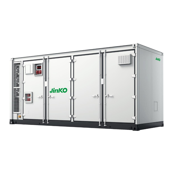
5.01MWh User Manual for liquid-cooled ESS 3.3 Exterior Design for the Energy Storage Systems 3.3.1 Enclosure aesthetics The container structure design mainly includes shape, steel structure selection, shell protection, container inlet and outlet lines, etc. The specific design is as follows: Overall dimensions of container: 20-foot standard high container with overall dimensions of 6058×2438×2896mm (20HQ);... - Page 25 5.01MWh User Manual for liquid-cooled ESS The enclosure aesthetics with dimensions of the container are shown in the figure: Front View Top View All rights reserved © JinkoSolar Co., Ltd...
- Page 26 5.01MWh User Manual for liquid-cooled ESS Side View Bottom View Figure 3-3-1 Schematic diagram of 20-foot container layout *Please note: The image provided is for illustrative purposes only. The actual product may vary. All rights reserved © JinkoSolar Co., Ltd...
-
Page 27: Ventilation Design
5.01MWh User Manual for liquid-cooled ESS 3.3.2 Ventilation Design Containers are designed with a "bottom-in, top-out" ventilation scheme, as shown in the figure below: Figure 3-3-2 Schematic diagram of container ventilation * Please note: The image provided is for illustrative purposes only. The actual product may vary. 3.4 Internal Design for the Energy Storage Systems 3.4.1 Composition of Internal Equipment The 5.01MWh system consists of 12 sets of 418KWh battery clusters, which are integrated and... -
Page 28: High Voltage Box
5.01MWh User Manual for liquid-cooled ESS Figure 3-4-1 Schematic diagram of container interior 3.4.2 High Voltage Box High-voltage box is a kind of high-voltage power circuit management unit designed for energy storage system, which is an intermediate unit connecting battery cluster and energy storage converter. High-voltage box has the functions of battery cluster voltage, battery cluster current collection, battery cluster circuit contactor control and protection, summarizing the data uploaded by the first-level BMS (BMU), and realizing the information communication with the third-level BMS... - Page 29 5.01MWh User Manual for liquid-cooled ESS switching power supply and other components. The high-voltage control box has been designed with full consideration of the electrical characteristics of each component, heat dissipation performance, safety performance and operability and maintainability, with reasonable space layout, featuring compact structure, flexible configuration, safety and reliability.
-
Page 30: Cell
5.01MWh User Manual for liquid-cooled ESS 3.4.3 Cell This design scheme adopts the mainstream 314Ah Ferrous lithium phosphate (LFP) square aluminum shell battery, and the parameters of the cell are as follows: Table Parameters for Cell: 3.2V 314Ah Parameter Value Rated capacity 314Ah Rated voltage... -
Page 31: Battery Pack
5.01MWh User Manual for liquid-cooled ESS 3.4.4 Battery PACK The design of battery PACK is to design batteries in series. According to the size of the battery PACK and the selected cell, the electrical box is connected in series with 104 cells. After series connection, the battery PACK is of 1P104S and the voltage is 332.8V. -
Page 32: Battery Rack
5.01MWh User Manual for liquid-cooled ESS 3.4.5 Battery RACK Battery cluster is mainly used to install battery PACK, high-voltage box and supporting wires and cables. The high-voltage box includes BCU, high-voltage and low-voltage electrical protection parts, etc .The design of battery cluster adopts a layered design, and the appearance of cabinet adopts maintenance-free technology .The battery cluster of this project is mainly equipped with 4 battery PACKs and 1 high-voltage box. -
Page 33: Integrated Cabinet
5.01MWh User Manual for liquid-cooled ESS 3.4.6 Integrated Cabinet 1) The integrated cabinet provides high-voltage DC bus parallel convergence for 12 418kWh battery clusters, and is equipped with lightning protection devices; 2) The integrated cabinet provides system emergency exit switch and function for 12 battery clusters and battery management system;... -
Page 34: Thermal Management Design Of The Container
5.01MWh User Manual for liquid-cooled ESS Wiring design of integrated cabinet 1) The installation and wiring of components in the integrated cabinet are neat and reliable, their layout is reasonable, and their electrical insulation meets the relevant standards. 2) The distribution of DC circuits in the integrated cabinet is reasonable and clear, and the incoming and outgoing lines adopt well-known brand terminals, with isolation protection between the terminals;... -
Page 35: Liquid-Cooled System
5.01MWh User Manual for liquid-cooled ESS maximum battery temperature of this product is ≤35℃, and the temperature difference is ≤4℃. The thermal management system of electrical room mainly adopts door-mounted industrial air conditioner (rated refrigeration capacity of 1.5kW) for air cooling circulation, which provides a working environment with reasonable temperature and humidity for indoor electrical components. -
Page 36: Liquid-Cooled Pipeline
5.01MWh User Manual for liquid-cooled ESS 6) The refrigerant is evaporated in the plate heat exchanger and absorbs the heat of the coolant. 7) The circulating water pump sends the coolant to the plate heat exchanger for heat exchange with the refrigerant, and sends the cooled coolant to the container to cool the battery pack. Parameter name Parameter value Operating voltage range... -
Page 37: Leakage Monitoring And Response
5.01MWh User Manual for liquid-cooled ESS 3.4.7.3 Leakage Monitoring and Response Reduce the risk of fluid leakage 1) The lower box and liquid-cooled plate are integrated and designed, no joints and leaks inside the PACK; 2) The nylon hose used in the primary pipeline can effectively absorb the assembly tolerance, and the sealing form is changed from stainless steel chuck to quick insertion form with lower risk of vibration resistance and impact leakage;... - Page 38 5.01MWh User Manual for liquid-cooled ESS manage the high voltage and heat, coordinate the automatic battery balance function of the whole energy storage system, and automatically calibrate the SOC according to the calculation when necessary .The block diagram of the battery management system is shown below. Figure 3-4-8-1 Block diagram of battery management system SCU(Level 3 BMS), is a kind of control and management host for energy storage battery management system, which carries out numerical calculation, performance analysis, alarm...
-
Page 39: Scu Layout
5.01MWh User Manual for liquid-cooled ESS 3.4.8.2 SCU layout Figure 3-4-8-2 SCU front & back layout All rights reserved © JinkoSolar Co., Ltd... -
Page 40: Scu Port Definition And Pin Order
5.01MWh User Manual for liquid-cooled ESS 3.4.8.3 SCU Port Definition and Pin Order Figure 3-4-8-3 Schematic diagram of SCU interface * Please note: The image provided is for illustrative purposes only. 1) RS485 PORT J12 (EDG-3.81MM Spaced double row 12Pin connector) Function RS485_CH4_A RS485_CH4_B... - Page 41 5.01MWh User Manual for liquid-cooled ESS RS485_CH2_B SHELL_EARTH SHELL_EARTH RS485_CH1_A RS485_CH1_B 2) RS485&CAN PORT J13 (EDG-3.81MM Spaced double row 10Pin connector) PIN No. Signal Name CAN2_H CAN2_L SHELL_EARTH SHELL_EARTH CAN1_H CAN1_L SHELL_EARTH SHELL_EARTH RS485_CH5_A RS485_CH5_B 3) RS485&CAN PORT J21 (EDG-3.81MM Spaced double row 6pin connector) PIN No.
- Page 42 5.01MWh User Manual for liquid-cooled ESS TEMP_NTC2 TEMP_NTC1 ADC4 ADC3 ADC2 ADC1 5) 4.2.4RS232 Debugging serial port J10 (EDG-3.81MM spaced 3Pin connector) PIN No. Signal Name DBG_TXD DBG_RXD 6) 4.2.5PWR-IN PORT J2 (EDG-3.81MM Spaced single row 2Pin connector) PIN No. Signal Name PWR_IN GND_PWR_IN...
-
Page 43: Ethernet Switches
5.01MWh User Manual for liquid-cooled ESS REPLAY5_OUT2 GND_PWR_IN GND_PWR_IN VCC_1A_OUT3 VCC_1A_OUT2 VCC_1A_OUT1 VCC_1A_OUT0 8) 4.2.7DI PORT J18 (EDG-3.81MM Spaced double row 18Pin connector) PIN No. Signal PIN No. Signal Name Name DIN_01 DIN_02 DIN_03 DIN_04 GND_DIN_1 GND_DIN_2 DIN_05 DIN_06 DIN_07 DIN_08 DIN_09 DIN_10... -
Page 44: Switch Features And Benefits
5.01MWh User Manual for liquid-cooled ESS Figure 3-4-9-1 EDS-2018-ML diagram 3.4.9.2 Switch Features and Benefits ➢ Two Gigabit Ethernet ports are used for the uplink and flexible interface design for high-bandwidth data transmission ➢ Supports QoS and processes critical data in high-traffic transmission ➢... -
Page 45: Interfaces And Functions For Ups
5.01MWh User Manual for liquid-cooled ESS 3.4.10.2 Interfaces and Functions for UPS The interface of UPS is shown as below: Figure 3-4-10-2 Schematic diagram for UPS interface Name Instruction - Clear display of information about the UPS status and measured values Graphic LCD display - Enhanced Configuration Features... -
Page 46: Design Of Video Surveillance System (Optional)
5.01MWh User Manual for liquid-cooled ESS Figure 3-4-11 Schematic diagram for Air Conditioner Installation on the energy storage system 3.4.12 Design of Video Surveillance System (Optional) The video surveillance system is mainly responsible for all-weather routine video monitoring of main electrical equipment and installation sites, and can be linked with other subsystems for alarm to meet the requirements of operation management for safety and patrol inspection. -
Page 47: Primary Diagram For The Energy Storage System
5.01MWh User Manual for liquid-cooled ESS In this scheme, two high-definition cameras are arranged in the container, and the power supply in thecontainer is used to ensure that the equipment is on-line 24 hours a day, and the network signals of the cameras are converted into optical signals with multi-port optical fiber transceivers for long-distance transmission. -
Page 48: Lifting, Transportation And Storage
5.01MWh User Manual for liquid-cooled ESS 4. Lifting, Transportation and Storage 4.1 Lifting Operation 4.1.1 Precautions for Lifting ➢ In the process of lifting, it is necessary to operate in strict accordance with the safety regulations of the crane. ➢ It is strictly prohibited to keep people stand there within 10 meters of the operation area, especially under the lifting arm and Warning under the lifting or moving machine, to avoid accidents. -
Page 49: System
5.01MWh User Manual for liquid-cooled ESS 4.1.4 Schematic Diagram on Lifting and Installation for Liquid-cooled Energy Storage System Figure 4-1 Schematic Diagram on Lifting for Liquid-cooled energy storage system All rights reserved © JinkoSolar Co., Ltd... -
Page 50: Transportation
5.01MWh User Manual for liquid-cooled ESS 4.2 Transportation Liquid-cooled energy storage system containers are suitable for land and sea transportation, and should be sheltered and sun-protected during transportation, civilized loading and unloading, and direct rain, snow and mechanical impact should be avoided during transportation. 4.2.1 Environmental Requirements for Transportation According to the characteristics of the battery, the battery pack should follow the below requirements during storage and transportation to maximize the protection of battery performance:... -
Page 51: Road Transportation
5.01MWh User Manual for liquid-cooled ESS Figure 4-3 Packaging Schematic on Tarpaulin 3) For sea transportation, it is necessary to add the relevant markings certified by the classification society: box master code, box number, weight and other relevant markings; 4) For ocean shipments, meet MSDS certification and affix a Class 9 Dangerous Goods label; 4.2.3 Road Transportation 1) Obey the traffic rules;... -
Page 52: Storage
5.01MWh User Manual for liquid-cooled ESS 4.3 Storage Considering storage,system should be placed in a dry warehouse, shall not be exposed to sunlight and rain. Harmful gases, flammable, explosive products and corrosive chemicals are not allowed in the warehouse, avoid mechanical shock, heavy pressure and strong magnetic field effect, avoid direct sunlight, no less than 2m away from the heat source, and at least 50cm away from the wall, window or air inlet. -
Page 53: Foundation Building
5.01MWh User Manual for liquid-cooled ESS 5. Foundation Building When selecting the site for the foundation, please follow the principles below: Climatic environment, soil and geological conditions (e.g. stress wave emission, underground water level) and other characteristics of the place where this liquid-cooled energy storage system is installed should be fully considered. -
Page 54: Equipment Installation
5.01MWh User Manual for liquid-cooled ESS 6. Equipment Installation 6.1 Installation Instructions The internal equipment of the Liquid-cooled energy storage system has been reliably connected and tested before leaving the factory, and it is necessary to install and fix the container box, connect the power cables to the DC side of the PCS, do connection on the external signal cables, do connection on the external auxiliary power supply cables, and connect the container to the ground on the project site. -
Page 55: Pre-Installation
5.01MWh User Manual for liquid-cooled ESS The installation steps on liquid-cooled energy storage system is described in detail as Table 6-1 shown: Table6-1 Detailed description of the installation steps Installation protocol Installation steps ➢ Check containers and functional cabinets for cosmetic damage. -
Page 56: Environment Requirements For Installation
5.01MWh User Manual for liquid-cooled ESS 6.2.3 Environment Requirements for Installation The box of liquid-cooled energy storage system on installation environment should follow the below requirements: Table6-2 Requirements for installation environment on box of Liquid-cooled energy storage system Projects Requirement Land Surface Inclination≤1°... -
Page 57: Ground Connection For Liquid-Cooled Container
5.01MWh User Manual for liquid-cooled ESS Bolt connection is to connect the four corner pieces at the bottom of the container with the embedded support with a set of T-bolt groups, and the fixing method is as follows: Figure 6-2-4-1 (2) Schematic diagram of container fixing by bolt connection 6.2.4.2 Ground Connection for Liquid-cooled Container The bolt fixing point of the container is reliably connected with the non-functional conductor of the whole container. -
Page 58: Electrical Connections
5.01MWh User Manual for liquid-cooled ESS Grounding bar Figure 6-2-4-2 schematic diagram of container grounding bar position、 6.3 Electrical Connections 6.3.1 Precautions for Electrical Safety High voltage danger! Danger of electric shock! ➢ Do not touch energized parts! ➢ Make sure that the AC and DC sides are not energized before Danger installation. -
Page 59: Preparation Before Cable Connection
5.01MWh User Manual for liquid-cooled ESS When an external short-circuit occurs in the RACK circuit and the high-voltage box fuse generates a protective action, the fuse in the high-voltage box must be replaced. Warning 6.3.2 Preparation before Cable Connection 6.3.2.1 Preparation for Installation Tools Tool Legends Insulated gloves... - Page 60 5.01MWh User Manual for liquid-cooled ESS Wire Strippers Hydraulic Clamp Heat guns Multimeters Torque wrenches Marker pens All rights reserved © JinkoSolar Co., Ltd...
-
Page 61: Preparation For Cable
5.01MWh User Manual for liquid-cooled ESS 6.3.2.2 Preparation for Cable The cable selected must follow the below conditions: ➢ Have adequate current-carrying ability. The current-carrying ability of the conductor includes, but is not limited to, the following factors: - Environment conditions - Type of conductor insulation - The way to lay the cable - Cable material and cross-sectional area... -
Page 62: Schematic Diagram For The Hole At The Bottom Of The Liquid-Cooled Container
5.01MWh User Manual for liquid-cooled ESS Figure 6-3-3 Schematic diagram of the layout of power lines and signal lines in the container. 6.3.3.1 Schematic Diagram for the Hole at the Bottom of the Liquid-cooled Container The bottom of the energy storage container is equipped with a DC power cable inlet on the PCS side, an external communication line port, and an external auxiliary power supply port, with detailed hole locations and hole sizes shown in Figure 6-3: Figure 6-3-3-1 Schematic diagram of the hole at the bottom of the liquid-cooled container... -
Page 63: Interface Diagram For Integrated Cabinet
5.01MWh User Manual for liquid-cooled ESS Name Quantity Remark External auxiliary Hole diameter: 60mm power cable port Communication cable Hole diameter: 60mm port DC power cable port on Hole diameter: 120mm PCS side 6.3.4 Interface Diagram for Integrated Cabinet 1) Power interface A power connection port connected to PCS is reserved in the container, which is located at the terminal of the integrated cabinet .See the following figure: Figure 6-3-4 External power connection port of confluence cabinet... -
Page 64: Interface Port For Dc Cable
5.01MWh User Manual for liquid-cooled ESS The internal wiring of the liquid-cooled energy storage system cabinet has been completed before shipment, and users only need to connect the external wiring. The external interfaces of the integrated cabinet include DC side cable wiring holes, external auxiliary power supply interface and external communication ports, and the specific cable connection port instructions are shown as Table 6-3-4:... - Page 65 5.01MWh User Manual for liquid-cooled ESS Figure 6-3-4-1 (1) Interface Port Schematic diagram of DC cable on integrated cabinet Recommended terminal block models for DC cables are shown as Table 6-4: Table 6-4 Recommended Terminal Block Models for DC Cable Item Description UL: 24 pcs of 1* 300kcmil AWG copper core power cables,...
-
Page 66: Connection Steps For Dc Cable
5.01MWh User Manual for liquid-cooled ESS Figure 6-3-4-1(2)Standardized Graph for Connection between Cable and Copper Copper Bar Copper nose Screws Spring washer Flat washer 6.3.4.2 Connection Steps for DC Cable Step 1: Confirm that each output switch in the front and rear stages of the integrated cabinet is disconnected;... -
Page 67: Interface Port For Ac Cable(Auxiliary Power Supply
5.01MWh User Manual for liquid-cooled ESS 6.3.4.3 Interface Port for AC Cable(Auxiliary Power Supply) Integrated cabinet provides external auxiliary power supply interface, location for cable connection is shown as Figure 6-3-4-3, the site needs to be according to the electrical wiring diagram for the corresponding wiring work. -
Page 68: Procedure For Cable Connection Between External Cable On Auxiliary Power Supply And Communication
5.01MWh User Manual for liquid-cooled ESS Figure 6-3-4-4 Interface for Communication Control and with the northbound communication fiber optic interface between Integrated cabinet and external PCS 6.3.4.5 Procedure for Cable Connection between External Cable on Auxiliary Power Supply and Communication Step 1: Pass the external cable for auxiliary power supply through the threading hole at the bottom of the container, use a screwdriver to connect it with the terminals reserved on the left side of the bottom of the integrated cabinet, and confirm that the connection is finished, and then fix the... -
Page 69: Cable Connection Between Battery
5.01MWh User Manual for liquid-cooled ESS ➢ Please do comprehensive inspection on all cables connected to ensure that there is no leakage and looseness. ➢ Tightly seal the holes and gaps around the integrated cabinet with fireproof and waterproof materials. ➢... -
Page 70: Requirements For Cable Connection
5.01MWh User Manual for liquid-cooled ESS gases. 6.4.1.3 Requirements for Cable Connection ➢ Please connect the primary and secondary connected cables to the equipment then do confirm on following the connection schematic; ➢ Ensure the correct polarity of the cables when connecting to prevent short-circuit and other dangerous situations;... - Page 71 5.01MWh User Manual for liquid-cooled ESS Communication cable Step1: It is necessary to wear protective equipment such as insulated gloves and insulated shoes before connecting power cables; Step2: Open the door of battery compartment and prepare each cluster of cables for connection. Turn the DC circuit breaker of high voltage box to the OFF position before connecting the power and communication cables between the PACKs and between the PACKs and the high voltage box;...
- Page 72 5.01MWh User Manual for liquid-cooled ESS 2) Plug the communication cable connector into the slave connector of the high voltage box; Figure 6-4-2 (3) Image of communication cable connector on HV BOX Step4:Connect the power cables between PACKs and the high voltage box, with a RACK as example: 1) Connect the positive terminal B+ of PACK1 to the negative terminal B- of PACK2;...
- Page 73 5.01MWh User Manual for liquid-cooled ESS Figure 6-4-2 (6) Image of communication and power cables in Rack •The color of Positive plug is orange, for negative plug is black. •The positive terminal of the plug needs to be inserted into the positive connector and the negative terminal of plug needs to be inserted into the negative connector.
-
Page 74: Product Operation
5.01MWh User Manual for liquid-cooled ESS 7. Product Operation 7.1 Liquid-cooled Energy Storage System Power-up Process 7.1.1 Pre-power-up Check 1)Check that the DC circuit breaker on the high voltage box panel is in the disconnected state; Figure 7-1-1 (1) HV BOX circuit breaker 2)... -
Page 75: Liquid-Cooled Energy Storage System Power-Up Procedure
5.01MWh User Manual for liquid-cooled ESS 4)Check that the communication and power harnesses as well as the power cables are properly connected on the high voltage box; 5)Check the LAN port connections in the integrated cabinet for problems. Figure 7-1-1 (3) LAN port 7.1.2 Liquid-cooled Energy Storage System Power-up Procedure Note: For all the switch details, please refer to the below table. - Page 76 5.01MWh User Manual for liquid-cooled ESS 5) Close operation control system switch QF227; 6) Close the BMS I/O switch power switch QF224; 7) Close the video surveillance system switch QF221.1; 8) Close the fire ventilation system switch QF222; 9) Close the high voltage box power supply switch QF227.1; 10) Close the HVAC power switch QF216;...
- Page 77 5.01MWh User Manual for liquid-cooled ESS Name Function QF207 AC side main Circuit breaker QF209 liquid-cooled system switch QF221 UPS switch QF223 Fire main switch QF227 Control system switch QF224 BMS I/O switch power switch QF221.1 video surveillance system switch QF222 fire ventilation system switch QF227.1...
-
Page 78: Liquid-Cooled Energy Storage System Power-Down Procedure
5.01MWh User Manual for liquid-cooled ESS 7.1.3 Liquid-cooled Energy Storage System Power-down Procedure Step 1: Disconnect the DC circuit breakers from each rack high voltage box; Step 2: 1) Turn off the UPS power; 2) Disconnect the HVAC power switch; 3) Disconnect the high voltage box power supply switch;... -
Page 79: List Of Commissioning For Energy Storage System
5.01MWh User Manual for liquid-cooled ESS 7.2 List of Commissioning for Energy Storage System Test Item Description Results OK■ Box shell flat and the color is uniform Exterior Clear marking, complete and correct Inspection OK■ silk-screening Check screws for looseness, slipped teeth, OK■... -
Page 80: Fire Fighting Instructions
5.01MWh User Manual for liquid-cooled ESS 8.Fire Fighting Instructions The energy storage system is equipped with an automatic fire extinguishing system, and the fire switch shall not be triggered arbitrarily Warning in non-emergency situations. 8.1 General Provision Please comply with the fire codes and regulations of the country/region where the project is located. - Page 81 5.01MWh User Manual for liquid-cooled ESS Figure 8-2 (1) Schematic diagram of fire protection system components Figure 8-2 (2) Schematic diagram of fire detectors components All rights reserved © JinkoSolar Co., Ltd...
- Page 82 5.01MWh User Manual for liquid-cooled ESS Figure 8-2 (3) Image of combustible gas detector Figure 8-2 (4) Image of temperature detector Figure 8-2 (5) Image of smoke detector All rights reserved © JinkoSolar Co., Ltd...
- Page 83 5.01MWh User Manual for liquid-cooled ESS Figure 8-2 (6) Image of fire control panel and gas cylinde Figure 8-2 (7) Image of pressure relief port All rights reserved © JinkoSolar Co., Ltd...
- Page 84 5.01MWh User Manual for liquid-cooled ESS Figure 8-2 (8) Image of air inlet Figure 8-2 (9) Image of air outlet Figure 8-2 (10) Image of external DN65 water supply port for water fire fighting * Please note: The image provided is for illustrative purposes only. The actual product may vary. All rights reserved ©...
-
Page 85: Gas Fire Extinguishers
5.01MWh User Manual for liquid-cooled ESS 8.3 Gas Fire Extinguishers 1) The fire extinguishing system has three starting modes: automatic control, manual control and mechanical emergency operation. 2) The fire extinguishing system can automatically detect a fire, give an alarm, automatically start, operate the related equipment interlocked with the system, and release the fire extinguishing agent. -
Page 86: Water Fire Fighting System
5.01MWh User Manual for liquid-cooled ESS 8.4 Water Fire Fighting System As the last protective barrier of the fire fighting system, the water firefighting system is an artificially controllable independent fire protection system, with standard fire protection water interface (DN65) reserved outside the battery compartment, and the fire protection water pipeline inside the battery compartment is designed with variable-diameter steel pipe. -
Page 87: Temperature Sensors
5.01MWh User Manual for liquid-cooled ESS 8.5 Temperature Sensors The Series DCD-190 Temperature Sensors utilize a dual thermistor network which provides a voltage output proportional to the outside air temperature. Figure 8-5 Schematic diagram for temperature sensors on energy storage systems 8.6 Photoelectric Smoke Sensors Series SOC-24V photoelectric smoke sensors utilize the light scattering principle to detect thermal runaway scenarios such as slow burning or smothering. -
Page 88: Soc Calibration Instructions
5.01MWh User Manual for liquid-cooled ESS 9. SOC Calibration instructions With the long time operation of the energy storage system, due to the self-discharge of the battery, process differences and current collection accuracy will lead to SOC error and it is constantly getting bigger. -
Page 89: Battery System Maintenance Instructions
5.01MWh User Manual for liquid-cooled ESS 10. Battery System Maintenance Instructions Explanation of terms Term Description Normal Refers to systems that work on a daily basis operation Intermittent Refers to a system that operates at a variable frequency per month and operation cannot be guaranteed to work on a daily basis Unused for a... -
Page 90: Requirements For Use Of Systems That Haven't Been Used For A Long Time
5.01MWh User Manual for liquid-cooled ESS 10.2.3 Requirements for use of systems that haven’t been used for a long time ➢ SOC range of storage battery: 15%~40%, avoid long-term storage of battery cells below 15% SOC, and cut off power consuming equipment in time when the battery is not used for a long time. -
Page 91: Liquid -Cooled System Maintenance
5.01MWh User Manual for liquid-cooled ESS Check to make sure the environment is safe, the system is safe, and there are no alarms or malfunctions before performing battery maintenance operations 10.5 Liquid -cooled System Maintenance 10.5.1 Electrical System Maintenance The maintenance information of the Liquid-cooled electronic control system is shown in Table 10-1:... -
Page 92: Cabinet Outlook Maintenance
5.01MWh User Manual for liquid-cooled ESS 10.5.2 Cabinet Outlook Maintenance The maintenance information for the appearance of the Liquid-cooled units is shown in Table 10-2:: Table 10-2 Appearance maintenance of Liquid-cooled units Maintenance Maintenance Maintenance Detection Exception handling method Projects Standards Period method... -
Page 93: Condenser Maintenance
5.01MWh User Manual for liquid-cooled ESS 10.5.4 Condenser Maintenance The condenser maintenance information for Liquid-cooled systems is shown in Table 10-4: Table 10-4 Condenser maintenance for Liquid-cooled systems Maintenance Maintenance Maintenance Detection Exception handling method Projects Standards Period method Clean the condenser with Condenser free compressed air or a vacuum Condenser... -
Page 94: Maintenance For Fire Suppression System
5.01MWh User Manual for liquid-cooled ESS concentration of the coolant. Ethylene glycol is a substance that pollutes groundwater, so the equipment operator must comply with national and local regulations and must not . 10.6 Maintenance for Fire Suppression System Only regular fire system inspection can ensure the normal operation of the fire suppression system, and fire system maintenance content is shown in Table10-6:... - Page 95 5.01MWh User Manual for liquid-cooled ESS - Check for dust buildup - Check for corrosion - Check for damage pipe network - Ensure that the distribution network is securely installed. - Ensure nozzles are installed in the correct position - Make sure that the nozzle is not covered with dust, grease, or paint and that the spraying is not obstructed 7) all parts...
- Page 96 5.01MWh User Manual for liquid-cooled ESS JinkoSolar After Sales Service. Monthly inspection program plus performance Maintenance Every 3 months testing of all valve actuator components, personnel performance testing of all electrical equipment. Maintenance Maintenance program every 3 months plus Every 6 months personnel check medication doses.
-
Page 97: Diagnosis Of Common Abnormal Problems
5.01MWh User Manual for liquid-cooled ESS 11. Diagnosis of Common Abnormal Problems 11.1 System Alarm Handling 11.1.1 Liquid-cooled Unit Failure 11.1.1.1 Fan failure Failure Possible causes Inspection and maintenance phenomenon Liquid-cooled unit not Check if there is power at the power input of the powered up liquid-cooled unit. -
Page 98: Refrigeration System Failure
5.01MWh User Manual for liquid-cooled ESS 11.1.1.2 Refrigeration System Failure Failure Possible causes Inspection and maintenance phenomenon Not powered on Check the main power switch and check the operation (standby) display to see if the power is on. Loose circuit Tighten circuit connector. -
Page 99: Methods Of Handling Emergencies
5.01MWh User Manual for liquid-cooled ESS See "10.4 Replacing the electric heater and circulating water pump" for details. No heating Check whether the water outlet temperature and requirement heating set point are set reasonably. Loose circuit Fasten the circuit connectors. connection Electric Electric heating... -
Page 100: Battery Drop/Impact
5.01MWh User Manual for liquid-cooled ESS 11.2.3 Battery drop/impact ➢ In case of obvious odour, damage, smoke, fire, etc., evacuate personnel immediately, call the police in time, and contact professionals, who will use firefighting facilities to extinguish the fire while ensuring safety. ➢... -
Page 101: Appendix
5.01MWh User Manual for liquid-cooled ESS 12.Appendix 12.1 Inspection Program Inspection Abnormal Inspection items Yes/No method records Whether the fire extinguishing system Visual is complete Whether the fire extinguishing system Visual is within the validity period Whether the heat dissipation system is Visual complete Whether the air duct of the heat... - Page 102 5.01MWh User Manual for liquid-cooled ESS missing Is the maintenance switch (MSD) Visual complete and reliably installed? Is the water cooling pipe broken Visual Is there any bad odor in the battery Olfaction room? Is there any irritating odor in the Olfaction cabinet? Is there a burnt smell in the high...
- Page 103 5.01MWh User Manual for liquid-cooled ESS Service email: G_ESS.Service@jinkosolar.com Email: ESS.EU@jinkosolar.com Hotline: +49 40 2 853 851 820 Africa Email: G_ssa-techsupport@jinkosolar.com...
Need help?
Do you have a question about the JKE-5015K-2H-LAA and is the answer not in the manual?
Questions and answers