Table of Contents
Advertisement
Quick Links
Advertisement
Table of Contents

Summary of Contents for MINELLI Mira VARIO-DRIVE
- Page 1 Instruction Manual English (EN) Electric drive unit...
-
Page 2: Table Of Contents
Table of contents Safety Regulations ..........................2 Copyright © ............................3 Non-liability ............................4 Warranty ............................. 4 Declaration of conformity ......................... 5 Machine parts ............................ 6 Connections and type plate ......................7 Control box with type plate ....................7 Vario Drive assembly with hand grip ..................8 Controls Vario Drive .......................... -
Page 3: Safety Regulations
Power must be disconnected prior to any electrical work or repair operations! Repair operations may only be performed by the manufacturer (Minelli Corporation) or by the local Mira representative! Use only genuine MIRA spare parts that are listed in the respective instruction manuals! Avoid contact with the electrical circuits of the machine! =>... -
Page 4: Copyright
Copyright © The exclusive copyright of this instruction manual remains in the hands of the MINELLI Corporation (MIRA). This instruction manual is appointed to the operator and the corresponding employees. Minelli Corporation MIRA Division Mattenstrasse 3 8330 Pfäffikon ZH Switzerland For the provided technical documentation see the authorised person in chapter „Declaration of conformity“... -
Page 5: Non-Liability
Warranty In case of manufacturing or material defects Minelli Corporation will replace the defective part or parts at no charge within 12 months after the date of final purchase. No further claims can be covered under the warranty. -
Page 6: Declaration Of Conformity
Declaration of conformity 20.7.2023/ v1.5 Vario Drive | Serial-No.: 0318 © (subject to change without notice) -
Page 7: Machine Parts
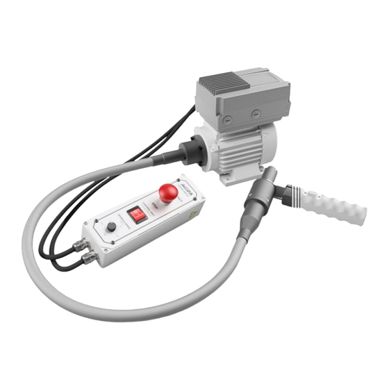
VARIO DRIVE (Series 0318) The Vario Drive system allows an efficient and fatique-proof refacing of valve seats via the manually operated MIRA valve seat refacing units (VGX-21, VG-91 etc.). Through the steady rotation of the electric drive unit, it is possible to accomplish a constant high-quality surface. The provided control box enables a stepless speed control between 0 to 200rpm and can be positioned individually with a magnetic clamp. -
Page 8: Connections And Type Plate
Connections and type plate The Vario Drive includes the modules Control box, Vario Drive assembly and hand grip with switch key button. The connection of these modules, among each other, is illustrated in chapter 9 on page 10 and schematically on chapter 12 on page 16. The type plate is located on the rear side of the Vario Drive control box. -
Page 9: Vario Drive Assembly With Hand Grip
7.2 Vario Drive assembly with hand grip Output of the cable for the hand grip, to the Vario Drive assembly (alongside the flexible shaft) Switch key button Input for the cable of the hand grip Potentiometer cable male to control box Earthing for Power cable HM-2000 EVO... -
Page 10: Controls Vario Drive
Controls Vario Drive Front plate control box Flexible shaft EMERGENCY STOP Hand grip ON-OFF Vario Drive Switch key button for spindle ON-OFF Potentiometer Spindle speed 0-200min Driving pin to VGX-21 device 20.7.2023/ v1.5 Vario Drive | Serial-No.: 0318 © (subject to change without notice) -
Page 11: Installation And Startup
Installation and startup The installation of the Vario Drive system can be carried out in two variations: Mounting on the HM-2000 EVO / Mounting to wall (AV-Mobile). The Vario Drive assembly will be installed on the respective workstation firstly, then followed by the fix installation / cable connection of the Vario Drive control box. Pay attention! The use of an external voltage transformer is required if the installed Vario Drive will be operated in a 110VAC power network! 9.1 Mounting on the HM-2000 EVO... -
Page 12: Mounting To Wall (Av-Mobile)
9.2 Mounting to wall (AV-Mobile) It is recommended to wall-mount the Vario Drive system if combining it with an AV-Mobile workstation. To use the entire working area of the Vario Drive and reach the controls in a comfortable manner, make sure the assembly will be installed approximate to the AV-Mobile workstation. -
Page 13: Connecting The Control Box
9.3 Connecting the control box On the rear side, the control box is equipped with two magnetic clamps and can therefore be positioned flexibly on a magnetic surface (metallic sheet, square tube etc.). ATTENTION! Pay attention that the control box must be positioned near the workstation, if an emergency occurs and the emergency stop has to be pushed down immediately! The control box must be connected in a de-energised mode to the Vario Drive assembly! Isolate the Vario Drive from the power network and secure it against unintended re-... -
Page 14: Connecting To The Power Network
9.4 Connecting to the power network 9.4.1 220-240VAC / 50-60Hz This is the standardised power network for operation in the following countries: Switzerland, EU, UK, Africa, Russia, Australia, Asia and parts of Latin America. => The Vario Drive control box can be connected, with the provided Schuko / Swiss type power cable, directly to the local 230VAC power network or to the multiple socket of the HM-2000 EVO workstation. -
Page 15: Handling And Operation
11. If using a voltage transformer: Is it connected correctly to the power network and functioning? If the malfunction still occurs after the troubleshooting, please refer to our technical support at MIRATOOL via sales@minelli.ch 20.7.2023/ v1.5 Vario Drive | Serial-No.: 0318 ©... -
Page 16: Spare Parts
Spare parts From Fabrication-No.: VD-102 Serial-No.: 0318 When ordering spare parts, the serial- and fabrication number must always be indicated. (1x) Flexible shaft 12042.3.2837 (5x) Glide shoe 12042.4.2374 (3x) Cable tie 1EKB09 (1x) Plug-in socket 1KGD00392 (2x) Fuse 6,3A 1ESI6300 (3x) Cable tie 1EKB04.5 (1x) Hand grip... -
Page 17: Schematic Diagramm
Schematic diagramm 12.1 Control box 20.7.2023/ v1.5 Vario Drive | Serial-No.: 0318 © (subject to change without notice) -
Page 18: Electric Motor + Frequency Transformer
12.2 Electric motor + frequency transformer 20.7.2023/ v1.5 Vario Drive | Serial-No.: 0318 © (subject to change without notice) -
Page 19: Hand Grip With Switch Key Button
12.3 Hand grip with switch key button 20.7.2023/ v1.5 Vario Drive | Serial-No.: 0318 © (subject to change without notice) -
Page 20: Maintenance
Maintenance Servicing and maintenance can be held at a minimum if the Vario Drive will be operated properly and without any modifications. The use of warm water and a cleaning cloth are recommended for cleaning the anodised and powder-coated surfaces. Do not use any abrasive cleanser (acid, base, wire wool etc.) for surface cleaning. -
Page 21: Fuse For Control Box
13.1 Fuse for control box The Vario Drive control box is secured with two 6,3A fuses on the power supply side. In case of replacing the fuses, please follow the steps below: ATTENTION! The Vario Drive control box must be connected in a de-energised mode! Isolate the control box from the power network and secure it against unintended re-powering! 1. -
Page 22: Technical Data
Technical data The following specifications are in context with the Vario Drive System. Specifications for other devices (VGX-21) and equipment can be reviewed in the respective instruction manuals. VARIO DRIVE Dimensions Vario Drive assembly: 400x175x285mm (width x depth x height) Dimensions Vario Drive control box: 80x100x285mm (width x depth x height) Weight:... - Page 23 Notes 20.7.2023/ v1.5 Vario Drive | Serial-No.: 0318 © (subject to change without notice)
- Page 24 Manufacturer and wordwide distributor: Your local distributor: MINELLI CORPORATION Mattenstrasse 3 8330 Pfäffikon ZH Switzerland www.miratool.ch 20.7.2023/ v1.5 Vario Drive | Serial-No.: 0318 © (subject to change without notice)
Need help?
Do you have a question about the Mira VARIO-DRIVE and is the answer not in the manual?
Questions and answers