Table of Contents
Advertisement
Quick Links
Advertisement
Table of Contents

Subscribe to Our Youtube Channel
Summary of Contents for HT Instruments I-V600
- Page 1 © Copyright HT ITALIA 2024 Release EN 2.00 - 11/07/2024...
-
Page 2: Table Of Contents
I-V600 TABLE OF CONTENTS SAFETY MEASURES AND PRECAUTIONS ............... 3 1.1. Preliminary instructions ..................... 3 1.2. During use ......................... 4 1.3. After use ..........................4 1.4. Definition of measurement category (overvoltage) ............4 GENERAL DESCRIPTION ................... 5 2.1. Foreword ........................... 5 2.2. - Page 3 I-V600 10. TECHNICAL SPECIFICATIONS ................86 10.1. Technical characteristics ....................86 10.2. General characteristics ....................87 10.3. Environmental conditions for use ..................88 10.4. Accessories ........................88 11. APPENDIX ......................... 89 11.1. Theoretical aspects of the I-V curve measurement ............89 11.1.1.
-
Page 4: Safety Measures And Precautions
I-V600 1. SAFETY MEASURES AND PRECAUTIONS This instrument has been designed to comply with the IEC/EN61010-1 Directive on electronic measurement equipment. Before and during measurement, carefully follow the instructions below and read all the notes preceded by the symbol • Do not take voltage or current measurements in humid environments •... -
Page 5: During Use
I-V600 1.2. DURING USE Read the following recommendations and instructions carefully: CAUTION • Failure to comply with the warnings and/or instructions may result in damage to the equipment and/or its components or personal injury to the operator • Do not touch any unused test terminal •... -
Page 6: General Description
I-V600 2. GENERAL DESCRIPTION 2.1. FOREWORD The instrument is designed to carry out performance measurements (I-V curve) and quick pre-testing (IVCK) of photovoltaic (PV) modules/strings in accordance with IEC/EN60891 and IEC/EN62446-1. 2.2. INSTRUMENT FUNCTIONS The instrument can perform tests on Monofacial and Bifacial modules/strings up to 1500VDC, 40ADC. -
Page 7: Preparation For Use
I-V600 3. PREPARATION FOR USE 3.1. INITIAL CHECKS The electronics and mechanics of the instrument have been carefully checked before shipment. Every precaution has been taken to ensure that the instrument is delivered in perfect condition. In any case, it is advisable to check it for any damage that may have occurred during transport. -
Page 8: Description Of Parts
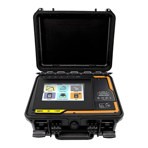
I-V600 4. DESCRIPTION OF PARTS 4.1. INSTRUMENT DESCRIPTION CAPTION: 1. C1, P1, C2, P2 inputs 2. Front panel 3. Touch-screen display 4. Key ON/OFF 5. START/STOP key 6. Battery compartment cover 7. Battery compartment cover fixing screw 8. Input for external power supply unit 9. -
Page 9: Description Of Function Keys
I-V600 CAPTION: 1. Battery compartment with battery polarity indicator 2. Slot for memory card 3. Memory card 4. Position of batteries inside compartment Fig. 3: Description of instrument battery compartment CAUTION The memory card (see Fig. 3 – part 3), in addition to managing saving data,... -
Page 10: Display Description
I-V600 4.3. DISPLAY DESCRIPTION CAPTION: 1. System bar 2. Active menu indication 3. IV Check function icon 4. System date/time indicator 5. WiFi connection active indicator 6. SOLAR03 connected indicator 7. Battery level indicator 8. Settings icon 9. SOLAR03 icon 10. -
Page 11: Side Menu
I-V600 4.5. SIDE MENU Tap on the icon " " to open/close the side bar/menu shown in the figure on the left. The following icons are available: HOME icon→, used to go back to the main menu from any screen displayed on the instrument REVERSE icon→, used to rotate the display for reading the... -
Page 12: Using Instrument While It Is Hanging And Attached To A Strap
I-V600 4.7. USING INSTRUMENT WHILE IT IS HANGING AND ATTACHED TO A STRAP For measurements where it is useful to hang the instrument, it is advisable to remove the cover from the case. To do so, proceed as follows: 1. Open the case and turn the two locking pins as shown in Fig. 5 Fig. - Page 13 I-V600 Fig. 7: Removing the cover from the instrument case - Step 3 4. Connect the SP-2003 strap (supplied) to the instrument as shown in Fig. 8. In this case, it is useful to rotate the display by 180° by tapping on the REVERSE key in the side menu (see §...
-
Page 14: Main Menu
I-V600 5. MAIN MENU instrument's main menu contains a series of icons used to access the internal measurements and settings. The instrument is controlled and programmed using the touch- screen display only, with no external function keys. The main menu consists of two pages. -
Page 15: Instrument Settings
I-V600 5.2. INSTRUMENT SETTINGS 1. Switch on the instrument using the ON/OFF key 2. Tap on the "Settings” icon on the main menu. The following screen will be displayed Fig. 10: General instrument settings 3. Drag each of the 7 thumb wheels to the right or left to set the desired value for each parameter in the “General”... -
Page 16: Information
I-V600 Fig. 11: Setting the date/time of the system 6. Drag each of the 7 thumb wheels to the right or left to set the desired value of each parameter in the "Date/Time” section. The following items are available: ➢ Year → to set the current year ➢... -
Page 17: Operating Instructions
I-V600 6. OPERATING INSTRUCTIONS DMM – MULTIMETER FUNCTION 6.1. In this function, the instrument displays the DC voltage value between the positive (+) and negative (-) poles of the PV module/string/field being tested, as well as the irradiance and temperature values when connected to a SOLAR03 remote unit. -
Page 18: Solar03 - Remote Unit
I-V600 6.2. SOLAR03 - REMOTE UNIT The SOLAR03 remote unit allows measuring the Irradiance and temperature values of the module, which are indispensable for the evaluation of the I-V curve, as well as the IVCK with values referenced to @STC. In general, the instrument and the SOLAR03 unit can operate in direct connection or synchronous recording. - Page 19 I-V600 Fig. 15: Pairing a SOLAR03 remote unit - Step 1 3. Switch on the SOLAR03 remote unit and select the "PAIRING…" menu (see the remote unit user manual) 4. Tap on the "Find” button on the instrument to start searching for the remote unit. The following screen appears on the display: Fig.
- Page 20 I-V600 6. Press ENTER on the SOLAR03 remote unit to complete the operation. After a few moments, the following screen will appear on the display: Fig. 18: Pairing a SOLAR03 remote unit - Step 4 7. From this point on, the two devices are paired and it is not necessary to repeat the above steps.
- Page 21 I-V600 9. Tap on to confirm or tap on to exit without proceeding. If yes, the following screen will appear: Fig. 20: Recording Activation on Remote Unit - Step 2 icon and the message "REC” appear on the display of the remote unit 10.
- Page 22 I-V600 Fig. 22: Deleting a remote unit 17. Tap on the key to confirm. The remote unit will be removed from the list; alternatively, tap on the key to exit without proceeding EN - 21...
-
Page 23: Db - Pv Modules Database Management
I-V600 DB – PV MODULES DATABASE MANAGEMENT 6.3. The instrument allows defining and saving up to approx. 63.000 modules. The parameters related to 1 module and the @STC conditions that can be set are shown in Table 1 below: Symbol Description Meas. - Page 24 I-V600 The initial screen of the Database function is shown in the following Fig. 24: Fig. 24: Database function initial screen in which there are two sections: Left-hand side ➢ The list of PV module manufacturers in alphabetical order, as entered by the user (manually or via the management software HTAgorà) up to that point.
-
Page 25: How To Define A New Pv Module
I-V600 6.3.1. How to define a new PV module 1. Tap on the "New” button on the main screen to open the programming screen. The following window will appear on the display: Fig. 25: Creating a new PV module - Step 1 2. -
Page 26: Modification Of A Pv Module
I-V600 Fig. 27: Creating a new PV module - Step 3 5. Tap on the "Save” key to save the defined module and return to the main screen, or tap on the "Exit” key to exit the setting without saving 6.3.2. -
Page 27: Searching For Pv Modules In The Database
I-V600 6.3.3. Searching for PV modules in the database CAUTION The search performed by the instrument is positional, i.e. the string entered will be searched within the lists starting from the first character to the left 1. Tap on the "Find” key on the main screen. The following window will appear on the display: Fig. -
Page 28: Deleting A Pv Module
I-V600 Fig. 31: Search by manufacturer 5. Use the alphanumeric virtual keyboard to enter the desired manufacturer's name or a keyword and tap on (ENTER) on the virtual keyboard to confirm. The searched manufacturer (if present) will be highlighted on the display (see Fig. 31) 6.3.4. -
Page 29: Restore Pv Modules Database
I-V600 6.3.5. Restore PV modules database If the PV modules database saved on the instrument is corrupt and is no longer accessible due to improper operations by the user or internal damages, it is possible to restore the factory database (default) in order to continue with the measurements To this end, proceed as follows: 1. -
Page 30: I-V - Measuring The I-V Curve
SOLAR03 after connecting these accessories to this remote unit The I-V600 instrument can acquire the module temperature value (also essential for calculating values under @STC conditions) as follows: • "Meas.": temperature measured via the PT305 probe connected to SOLAR03 •... -
Page 31: I-V Curve Test Without Remote Unit Solar03
I-V600 6.4.2. I-V Curve test without remote unit SOLAR03 CAUTION • The maximum voltage between the P1, C1, P2 and C2 inputs is 1500VDC. Do not measure voltages exceeding the limits given in this manual. • Do not perform tests on PV modules or strings connected to the DC/AC converter. - Page 32 I-V600 Fig. 35: Initial I-V test screen without remote unit on Monofacial modules 5. In the case of Bifacial modules, the screen of Fig. 36 is shown on the display. The following parameters are indicated: ➢ VPN voltage between positive and negative pole of the string ➢...
- Page 33 I-V600 Fig. 37: Settings parameters I-V test without remote unit 7. Tap on the "PV Module” key to change the PV module to be tested. The instrument opens the DB section, where a new module can be selected from the list in the DB section (see §...
- Page 34 I-V600 Fig. 38: I-V curve measurement result without remote unit 10. Tap on to save the measurement (see § 7.1) or the icon to exit without saving EN - 33...
-
Page 35: I-V Curve Test With Remote Unit Solar03 In Direct Connection
I-V600 6.4.3. I-V Curve test with remote unit SOLAR03 in direct connection CAUTION • The maximum voltage between the P1, C1, P2 and C2 inputs is 1500VDC. Do not measure voltages exceeding the limits given in this manual. • Do not perform tests on PV modules or strings connected to the DC/AC converter. - Page 36 I-V600 4. In the case of Monofacial modules, the Fig. 40 screen is present on the display. The following parameters are shown: ➢ VPN voltage between positive and negative pole of the string ➢ Module temperature (with PT305 probe connected) ➢...
- Page 37 I-V600 6. Tap on the "Settings” key (Monofacial module reference). The following screen is shown in Fig. 42. The following parameters are given: ➢ References of the currently selected module ➢ Parameters of the test string to be programmed ➢ Icon...
- Page 38 I-V600 10. Assemble the stem onto the disk of the accessory M304 and keep it resting on the module’s surface. Check that the shadow of the stem on the disk falls within the internal “limit concentric circle” of the disk itself (see picture).
- Page 39 I-V600 ➢ Nominal values of the module being tested under STC conditions as defined in the internal DB (see § 6.3) ➢ Measurement results calculated under STC conditions as a function of irradiance values measured by the connected SOLAR03 remote unit ➢...
- Page 40 I-V600 Fig. 46: Example of power measurement result - STC curve CAUTION • The instrument refers all the values to one module only under STC condition • The string voltage obtained at OPC indicates the total measured value. Together with the measured current, the instrument calculates the I-V curve @ OPC which is then translated to the @STC conditions 16.
-
Page 41: I-V Curve Test With Remote Unit Solar03 In Synchronous Recording
I-V600 6.4.4. I-V Curve test with remote unit SOLAR03 in synchronous recording Irradiance and temperature measurements (if the instrument is set to temperature measurement mode "Meas.") via SOLAR03 remote unit in synchronous recording are recommended if the distance between the modules and the instrument is significant. On the... - Page 42 I-V600 4. Tap on the "SOLAR03” key to access the control and management section of the SOLAR03 remote unit (see § 6.2). Check that only one remote unit is active and connected to the instrument 5. Tap on the "Run/Stop” key to start recording on the connected remote unit; the following screen will be displayed: Fig.
- Page 43 I-V600 Step 2 8. Move the remote unit close to the modules and connect the irradiance and temperature probes (if necessary) as shown in Fig. 47 or Fig. 48 – middle side part. In particular: ➢ In case of Monofacial modules → position the reference cell HT305 onto the front surface of module (F) and at input “INP1”...
- Page 44 I-V600 11. In the case of Bifacial modules, the screen Fig. 52 is shown on the display. The following parameters are indicated: ➢ VPN voltage between positive and negative pole of the string ➢ Module temperature with “- - -“ indication as the remote unit is not connected ➢...
- Page 45 I-V600 13. Tap on the "PV Module” key to change the PV module to be tested. The instrument opens the DB section, where a new module can be selected from the list in the DB section (see § 6.3) 14. Drag each of the 5 available thumb wheels to the right or left to set the desired value of the following parameters: ➢...
- Page 46 I-V600 16. Press the START/STOP key (or Start on the display) to activate the tests. If there are no error conditions, the instrument will show the icon " on the display for a few moments together with the message "Measuring..." The test can take up to approximately 20 seconds, depending on the open circuit voltage and module parameters.
- Page 47 I-V600 21. Tap on the key to confirm or on the key to exit without proceeding 22. The synchronization of the pending @OPC measurements, the translation of the @STC values and the subsequent saving are performed automatically by the instrument. The “N.
-
Page 48: Interpretation Of Measurement Results
I-V600 6.4.5. Interpretation of measurement results The parameter measured and calculated by meter have the following meaning: Parameter Description Pmax Maximum module power (@STC) measured by the instrument P% Difference % of maximum measured power from nominal power (@ STC) - Page 49 I-V600 Application example (measurement with remote unit) ➢ Module name: JKM575N-72HL4-BDV (JINKO manufacturer) ➢ Module type: Bifacial ➢ Nominal power (@STC): 575W ➢ Tolerance Power (@STC): -0% / +3% ➢ Performance loss calculated: 1.3% ➢ Service year: 1 year ➢ Measured power (@STC): 547W Tol+ = Tol%(+) * Pnom = 0.03 * 575V = 17.3W...
-
Page 50: Anomalous Situations
I-V600 6.4.6. Anomalous situations If the instrument detects a voltage of -0.5V≤VPN≤15VDC at the P-N terminals of the string, it does not perform test, emits prolonged audible signal and displays the message shown in the screen alongside. Check the tension on the string If the instrument detects a voltage <-0.5VDC at the P-N terminals of... - Page 51 I-V600 If, with the remote unit active and connected (even in recording mode), the instrument detects an irradiance value below threshold (see § 5.2), it stops the test and returns to the main screen. Check threshold value and carry out the tests at...
- Page 52 I-V600 If, during the execution of an I-V or IVCK measurement, the open- circuit voltage (Voc) value is very different from that defined in the module database, the instrument does perform measurement and displays the message shown in the screen alongside.
- Page 53 I-V600 If the instrument detects, at the end of the test, a Voc too much different from the open-circuit voltage measured before starting the test, the message alongside is shown on the display This condition could be due to the...
-
Page 54: Ivck - Commissioning Test On Pv Modules And Strings
I-V600 IVCK – COMMISSIONING TEST ON PV MODULES AND STRINGS 6.5. 6.5.1. General information This function performs the following tests on a PV module/string by measuring only: ➢ Open-circuit voltage Voc of the PV string/module being tested, measured in OPC condition (OPerative Condition), i.e. -
Page 55: Ivck Test Without Remote Unit Solar03
I-V600 6.5.2. IVCK test without remote unit SOLAR03 CAUTION • The maximum voltage between the P1, C1, P2 and C2 inputs is 1500VDC. Do not measure voltages exceeding the limits given in this manual. • Do not perform tests on PV modules or strings connected to the DC/AC converter. - Page 56 I-V600 Fig. 57: Initial IVCK test screen without remote unit on Monofacial modules 8. In the case of Bifacial modules, the Fig. 58 screen is present on the display. The following parameters are shown: ➢ VPN voltage between positive and negative pole of the string ➢...
- Page 57 I-V600 Fig. 59: IVCK test parameter settings 10. Tap on the "PV Module” key to change the PV module to be tested. The instrument opens the DB section, where a new module can be selected from the list in the DB section (see §...
- Page 58 I-V600 CAUTION When START/STOP (or Start on the display) is pressed, the instrument may give various error messages (see § 6.4.6) and, as a result, fail to perform the test. Check and, if possible, eliminate the cause of the problem before proceeding.
- Page 59 I-V600 CAUTION • The average values of Voc and Isc are displayed on the result page. These values include the average values of Voc and Isc under OPC conditions calculated as a rolling average of the last 10 previously stored tests If the user has carried out and saved a number of tests <10 or reset the average...
-
Page 60: Ivck Test With Remote Unit Solar03 In Direct Connection
I-V600 6.5.3. IVCK test with remote unit SOLAR03 in direct connection Irradiance and temperature measurements (if the instrument is set to temperature measurement mode "Meas.") using a SOLAR03 remote unit directed connected to the device via Bluetooth are recommended when irradiance conditions are unstable or when a comparison with the nominal values of the module declared by the manufacturer is required. - Page 61 I-V600 4. In the case of Monofacial modules, the Fig. 64 screen is present on the display. The following parameters are shown: ➢ VPN voltage between positive and negative pole of the string ➢ Module temperature (with PT305 probe connected) ➢...
- Page 62 I-V600 ➢ Voc and Isc (@STC) references of the currently selected module ➢ Parameters of the test string to be programmed ➢ Icon to save and return to the main screen, or icon to exit without saving Fig. 66: I-V curve measurement parameter settings 7.
- Page 63 I-V600 10. Press the START/STOP key (or Start on the display) to activate the test. If there are no error conditions, the instrument will show the icon “ on the display for a few moments together with the message "Measuring..." The test can take up to approximately 20 seconds, depending on the open circuit voltage and module parameters.
-
Page 64: Ivck Test With Remote Unit Solar03 In Synchronous Recording
I-V600 6.5.4. IVCK test with remote unit SOLAR03 in synchronous recording The Irradiation and temperature measurements (if the instrument is set in the “Meas” temperature measurement mode) by using the SOLAR03 remote unit connected in synchronous recording to the instrument are recommended if unstable irradiation... - Page 65 I-V600 Step 1 3. Move the SOLAR03 remote unit close to the instrument as shown in Fig. 69 or Fig. 70 – left side part 4. Turn on the SOLAR03 remote unit, pair it and connect it to the instrument as indicated in §...
- Page 66 I-V600 Step 2 8. Move the remote unit close to the modules and connect the irradiance and temperature probes (if necessary) as shown in Fig. 69 or Fig. 70 – middle side part. In particular: ➢ In case of Monofacial modules → position the reference cell HT305 onto the front surface of module (F) and at input “INP1”...
- Page 67 I-V600 10. In the case of Bifacial modules, the Fig. 74 screen is shown on the display. The following parameters are indicated: ➢ VPN voltage between positive and negative pole of the string ➢ Module temperature with "- - -" indication ➢...
- Page 68 I-V600 13. Drag each of the 5 available thumb wheels to the right or left in order to set the desired value of the following parameters: ➢ Num. Mod → to set the number of modules in the string being tested(max. 60) ➢...
- Page 69 I-V600 Fig. 76: IVCK test result @OPC with synchronous recording 17. Tap on the icon to save the measurements to the internal memory (see § 7.1), or on icon to exit without saving Step 3 18. At the end of the test session, disconnect the SOLAR03 remote unit, place it close to the instrument (see Fig.
- Page 70 I-V600 CAUTION The instrument translates @OPC results to @STC values when the following conditions occur: 19. Voltage Voc > Voc minimum = 15V 20. Frontal irradiance values (also valid for bifacial modules) detected as greater than the minimum threshold set on the instrument (>100W/m ) and stable (variation between the start and end of the measurement campaign ±20 W/m...
-
Page 71: Interpretation Of Measurement Results
I-V600 6.5.5. Interpretation of measurement results In general, the result of a test on a Voc and Isc measurement is determined by the following relationships: Measurements without remote unit (no irradiation and temperature) Note the following parameters: VocAve → average open voltage value calculated in the last 10 saved measurements IscAve →... - Page 72 I-V600 Measurements with remote unit (irradiation and temperature) Note the following parameters: VocNom → nominal open voltage value of Voc (declared by the manufacturer) IscNom → nominal short circuit current value of Isc (declared by the manufacturer) Voc (Tol+) = Tol%(+)Voc * VocNom → Positive tolerance value on Voc Voc (Tol-) = Tol%(-)Voc * VocNom →...
- Page 73 I-V600 Application example (measurement with remote unit) ➢ Module name: LR5-54HIH-410M (LONGI manufacturer) ➢ Module type: Mono-facial ➢ Declared nominal Voc voltage (@STC): 37.3V ➢ Declared nominal short circuit current Isc (@ STC): 13.88A ➢ Tolerance Voc: ±5% ➢ Tolerance Isc: ±10% ➢...
-
Page 74: Mem - Storage Of Results
I-V600 7. MEM - STORAGE OF RESULTS The instrument can store up to up to 9999 measurement results (I-V curves or IVCK tests). Test results can be organised and grouped in a structure similar to that of the photovoltaic system being tested by associating up to 3 different levels of markers for each of the memory locations used, in order to detail the corresponding location of the measurement. - Page 75 I-V600 Fig. 80: Saving Measurement Result - Step 3 4. With a first-level marker highlighted, tap on the “New” key to define a possible name for a second-level marker. The following screen will appear: Fig. 81: Saving Measurement Result - Step 4 5.
- Page 76 I-V600 6. With the second-level marker highlighted, tap on the “New” key to define a possible name for a third-level marker. The following screen will be displayed: Fig. 83: Saving Measurement Result - Step 6 7. Use the virtual alphanumeric keyboard to define the third-level marker (ex: "MODULE X") and touch the...
- Page 77 I-V600 9. Tap on the icon again to complete the saving process of the measurement under the blue highlighted marker (ex: third-level "MODULE X") and return to the main measurement screen 10. When a new first-level marker is required, tap on the "New first level” key shown on the following screen: Fig.
-
Page 78: Displaying Results
I-V600 7.2. DISPLAYING RESULTS 1. Tap on the "Memory” icon in the main menu to display the data. The following screen shows an example of displayed data Fig. 87: Displaying results 2. Tap on the desired marker on the left-hand side of the screen. On the right-hand side, the current memory location is shown, along with the measurements stored for that marker. - Page 79 I-V600 5. Tap on the "Current” key to display the I-V @STC curve. The following screen will appear: Fig. 89: Retrieving the I-V curve measurement results - Current curve @STC 6. Tap on the "Power” key to display the I-V @STC power curve as shown in the figure below: Fig.
- Page 80 I-V600 8. Tap on the "Current” key to display the I-V @OPC curve. The following screen will appear: Fig. 92: Retrieving the I-V curve measurement results - Current curve @OPC 9. Tap on the "Power” key to display the @OPC power curve. The following screen will appear: Fig.
-
Page 81: Deleting Results
I-V600 7.3. DELETING RESULTS 1. Tap on the "Memory” icon on the main menu to display the data (see Fig. 87) 2. Select (highlight in blue) a test on the screen and tap on the "Delete” key. The following message will appear on the display: Fig. - Page 82 I-V600 Fig. 97: Deleting an internal marker 7. Tap on the key to confirm the deletion of the marker together with any measurements it contains, or on the key to exit without proceeding EN - 81...
-
Page 83: Anomalous Situations
I-V600 7.3.1. Anomalous situations If a highlighted top-level marker containing some measurements is to be removed, the instrument will not proceed and will display the message shown in the figure. Remove all lower-level markers first If an attempt is made to delete a marker with the word "Markers"... - Page 84 I-V600 If, during saving, you try to associate a measurement with a marker in which the maximum number possible measurements are present (max 500), the instrument shows the message shown in the figure on the side and does not carry out operation.
-
Page 85: Connecting The Instrument To The Pc
I-V600 8. CONNECTING THE INSTRUMENT TO THE PC The PC is connected to the instrument via the USB-C port (see Fig. 2) using the C2010 cable supplied, or via a WiFi connection. The choice of connection type must be made within the management software HTAgorà... -
Page 86: Maintenance
I-V600 9. MAINTENANCE 9.1. GENERAL INFORMATION During use and storage, the recommendations in this manual must be followed to avoid possible damage or danger to the operator. Do not use the instrument in environments characterized by humidity or temperatures outside the environmental conditions indicated in §... -
Page 87: Technical Specifications
I-V600 10. TECHNICAL SPECIFICATIONS 10.1. TECHNICAL CHARACTERISTICS Accuracy stated as ± [%reading + (num. dgt*resolution)] at 23 °C ± 5 °C, <80%RH MULTIMETER FUNCTION DMM – DC Voltage Range [V] Resolution [V] Accuracy 3 1500 (1.0reading + 2dgt) I-V CURVE MEASUREMENTS AND IVCK TESTS... -
Page 88: General Characteristics
I-V600 10.2. GENERAL CHARACTERISTICS Reference guidelines Instrument safety: IEC/EN61010-1, IEC/EN61010-2-030 EMC: IEC/EN61326-1 Technical literature: IEC/EN61187 Safety of measuring accessories: IEC/EN61010-031 Measurements: IEC/EN60891, IEC/EN60904-1-2 (I-V curves) IEC/EN62446, IEC/EN60904-1-2 (IVCK test) PV module temperature (Auto): IEC/EN60904-5 EMC environment of use: portable, Class A, Group 1... -
Page 89: Environmental Conditions For Use
I-V600 10.3. ENVIRONMENTAL CONDITIONS FOR USE Reference temperature: 23° ± 5°C (73°F ± 41°F) Working temperature: -10°C ÷ 50°C (14°F ± 122°F) Permitted relative humidity: <80%RH Storage temperature: -20°C ÷ 60°C (-4°F ± 140°F) Storage humidity: <80%RH Max operating altitude:... -
Page 90: Appendix
I-V600 11. APPENDIX 11.1. THEORETICAL ASPECTS OF THE I-V CURVE MEASUREMENT The instrument is designed to perform tests and measurements on PV modules consisting of a suitable number of PV cells in order to determine their I-V (Current-Voltage) characteristic, which identifies them constructively, based on the reference standard... -
Page 91: Typical Errors On I-V Curves And Troubleshooting
I-V600 11.2. TYPICAL ERRORS ON I-V CURVES AND TROUBLESHOOTING Measurement Event Troubleshooting • The measured curve extrapolated to • No error, save data and Good measurement STC (blue) and the curve as move to next string to test declared manufacturer (black) of the modules match. - Page 92 I-V600 • Voltage drop on cables to PV • Check cables, connectors, Low voltage ratio Vmpp/Voc module string contacts, and string wirings • Check cable length and cross section • Check modules connections or oxidation • Replace affected modules • Small or partial shading of one •...
-
Page 93: Service
I-V600 12. SERVICE 12.1. WARRANTY CONDITIONS This unit is guaranteed against defects in materials and workmanship in accordance with the General Conditions of Sale. During the warranty period, all defective parts may be replaced and the manufacturer reserves the right to repair or replace the product. - Page 94 HT ITALIA SRL Via della Boaria, 40 48018 – Faenza (RA) – Italy WHERE T +39 0546 621002 | F +39 0546 621144 WE ARE M ht@ht-instruments.com | ht-instruments.com...
Need help?
Do you have a question about the I-V600 and is the answer not in the manual?
Questions and answers