Advertisement
Advertisement
Table of Contents

Summary of Contents for M2I MEX-PZC00
- Page 1 2022-10-12 User Manual Purge Controller MEX-PZC00 M2I Corporation...
-
Page 2: Information On This Manual
Preface We are pleased that you have chosen a quality product from M2I Corporation. Information on This Manual Knowledge of the basic safety regulations and additional training and experience in the area of explosion protection are essential for the safe handling and failure-free operation of the series purge and pressurization system. - Page 3 Safety Contents This document contains information that you need to use your product throughout the applicable stages of the product life cycle. These can include the following: Product identification Delivery, transport, and storage Mounting and installation Commissioning and operation ...
-
Page 4: Conditions Of Safe Use
General Information on Purge and Pressurization Purge and pressurization is one of the most versatile ignition protection classes. Purge and pressurization systems are based on the principle that in Zone 2/Class I, the gas mixture in the ambient atmosphere, which may ignite under certain circumstances, is removed from the housing by an initial purge process. -
Page 5: Unit Information
Equipment architecture max. enclosure size 10 m³ Operating mode fully automatic (FA) Series MEX-PZC00 Hazardous environment Supply Rated voltage 24V DC at 0.2 A 220 V AC, 60 Hz at 0.1 A without solenoid valve Supply voltage can be line-to-line or line-to-neutral, single phase... -
Page 6: Mechanical Specifications
Power consumption max. 2.7 W / 7.3 VA without valve Accuracy pressure readings: ± 3 % timers: ± 2 % Connection screw terminals—see manual Output K1: terminals, 1 x NO, enclosure power contacts, 0.5 A at 24 V DC, relays must be externally fused inrush current: 50 A K2: terminals, 1 x NO, alarm and control contacts, 0.5 A at 24 V DC, relays must be externally fused inrush current: 50 A... -
Page 7: Terminal Wiring
Terminal wiring Requirements 1. All applicable local and national wiring codes must be followed when wiring the system. See IEC 60079-14 for more information. 2. The power supply to this device shall have a separate disconnect. If placed in the hazardous area, it shall be rated for the area in which it is being installed. - Page 8 Dimensions Panel Cut-Out Dimensions...
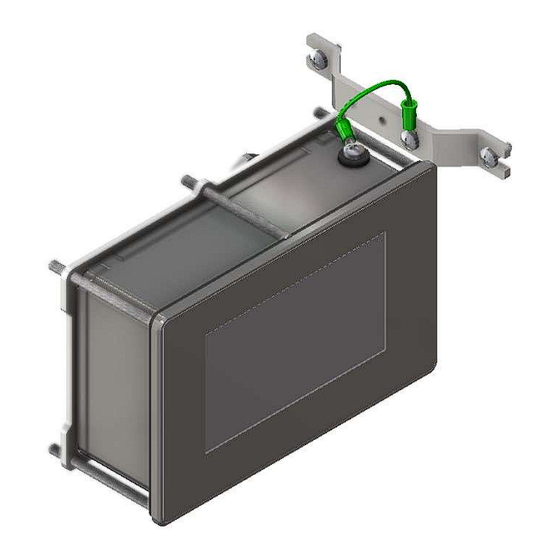
- Page 9 Installation & Operation Installation <Body> * The equipment shall only be used in an area of at least pollution degree 2, as defined in IEC 60664-1. * The equipment shall be installed in an enclosure that provides a minimum ingress protection of IP 54 in accordance with IEC 60079-0 * Use the IECEx Certified Cable gland.
- Page 10 <FG Cable> * Install the cross section of the power conductor to the cross section of the FG cable.
-
Page 11: Operation
Torque Requirements Torque 12 in lb (1.35Nm) Hardware Torque Main lid 12 in lb (1.36 Nm). M4 screws for mounting bracket 12 in lb (1.36Nm). Screws for mounting HUB 12 in lb (1.36 Nm). M12 plug 15 in lb (1.70 Nm). Panel mount bracket hardware Tighten evenly to a uniform gasket thickness of 1.3 mm to 1.7 mm Tighten until control unit is touching metal-to-metal around all... - Page 12 3. Program the unit using the user-interface display on the front. 4. Make sure the control valve is closed before applying pressure to the system. 5. Use a regulated pressure source to the valve. Set the regulated pressure to 2KPas or lower. Do not exceed the maximum pressure for the valve and tubing that is being used.
- Page 13 Programming User Interface Display 1 : Main Page Remained purge time Remained purge percentage Selected program id Graphic position current pressure Current pressure Setup Output status indicator of (K1,K2,K3)
- Page 14 Display 2 : Setup Page Purge Setup Available Setup Parameters Parameters Description Default Value boundary 1-5, * Select proper program for Purge Program select purge program (1-5) each environment. See [Table 2/3] Purge Time Timer set to purging 5:00 MIN : 120, SEC : 59 Pressure P1 Minimum pressure of enclosure Pressure P2...
- Page 15 Program ID Atmosphere in Other condition Program 1 Hazardous gas Program 2 Hazardous gas Program 3 Hazardous gas Program 4 Hazardous gas [Table 2] Program Flow ProID Output p* > P1 P1 < p < P2 During Purging P2 < p < p3 P3 <...
-
Page 16: Maintenance And Repair
This includes pressure readings within the specifications contained in this manual. When checking pressure measurements of the control unit, use calibrated equipment to determine the measurements, or contact a M2I representative or the factory to send the device back for function verification.
Need help?
Do you have a question about the MEX-PZC00 and is the answer not in the manual?
Questions and answers