Table of Contents
Advertisement
Quick Links
Advertisement
Table of Contents

Related Manuals for Merits E604


Summary of Contents for Merits E604
- Page 1 E604 STAIRLIFT Installation & Service MANUAL Merits Health Products Co., Ltd.
-
Page 2: Table Of Contents
E 6 0 4 I n s t a l l a t i o n a n d S e r v i c e M a n u a l Table of Contents 1. Introduction 1.1. Intended Use ............................. 1-1 1.2. - Page 3 E 6 0 4 I n s t a l l a t i o n a n d S e r v i c e M a n u a l 3.1.3 Wiring Diagram ..........................3-24 3.1.4 Error Codes: ............................ 3-26 3.1.5 Replace the Batteries ........................
-
Page 4: Introduction
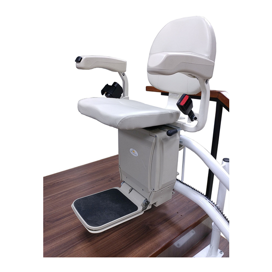
M a n u a l 1. Introduction The Merits Stairlift basically consists of four parts: the carriage, the footrest, the seat, and the rail. The stairlift is powered by the rechargeable batteries inside the carriage. There are safety sensors on upper and lower covers and bottom of footrest. -
Page 5: Warranty
M a n u a l 1.4. Warranty Merits Health Products Co., Ltd. warrants the Merits Stairlift to be free from defective workmanship and materials for a period of 1 year from the date of purchase. The rechargeable battery is warranted for 180 days from date of purchase. -
Page 6: Specifications
E 6 0 4 I n s t a l l a t i o n a n d S e r v i c e M a n u a l SPECIFICATIONS: Dimensions: - 1-3 -... - Page 7 E 6 0 4 I n s t a l l a t i o n a n d S e r v i c e M a n u a l Technical Specs: Load Capacity 120kg (265 lbs)@52° 0°~52° Note: According to ASME A18.1, no lift should be Range of Stair Angle installed to operate on an incline greater than 45...
-
Page 8: Installation
E 6 0 4 I n s t a l l a t i o n a n d S e r v i c e M a n u a l 2. Installation 2.1. Unpack and verify the shipment Tool Parts Knife... -
Page 9: Remove The Protecting Foam Of The Rails
E 6 0 4 I n s t a l l a t i o n a n d S e r v i c e M a n u a l 2.1.2. Remove the protecting foam of the Rails Remove the protecting foam of the Rails and unpack the Rail Foot Stands by using a knife. -
Page 10: Install The Rail Sections
E 6 0 4 I n s t a l l a t i o n a n d S e r v i c e M a n u a l 2.2. Install the Rail Sections Tool Parts Portable Hammer Drill Lubricant &... -
Page 11: Assemble The Rail Sections
E 6 0 4 I n s t a l l a t i o n a n d S e r v i c e M a n u a l b.) Insert the Wire Threader with the Wire Harness from the topmost Rail Section through the Lower Rail of each Rail Section. - Page 12 E 6 0 4 I n s t a l l a t i o n a n d S e r v i c e M a n u a l b.) Assemble the Rail Sections together one by one from the Top to the Bottom. Use the Quick F-Clamp to tighten the Upper and Lower Rails of each Rail Sections.
-
Page 13: Fix 2 Rail Sections With Spring Pins
E 6 0 4 I n s t a l l a t i o n a n d S e r v i c e M a n u a l 2.2.4. Fix 2 Rail Sections with Spring Pins a.) Align the Spring Pin holes on two Rail sections: The Spring Pins holes are located on the Upper Rail sections at about 2 CM down from the joint edge of 2 Rail Sections. -
Page 14: Adjust The Height Of Each Rail Section
E 6 0 4 I n s t a l l a t i o n a n d S e r v i c e M a n u a l 2.2.5. Adjust the height of each Rail Section a.) First, adjust the height of the Rail Foot Stand at Bottom, Middle &... -
Page 15: Install The Carriage To The Rail
E 6 0 4 I n s t a l l a t i o n a n d S e r v i c e M a n u a l 2.3.2. Install the Carriage to the Rail a.) Insert 2 Pin Stoppers to the Tube, this is to fix the carriage to avoid it from moving/ slipping while installing. - Page 16 E 6 0 4 I n s t a l l a t i o n a n d S e r v i c e M a n u a l b.) Insert the steel tube onto the Connecting Tube in the Upper Rail. And align the Swing Head to the Shuttle Guide in the Lower Rail.
-
Page 17: Fix The Rail Foot Stands Onto The Stair Tread
E 6 0 4 I n s t a l l a t i o n a n d S e r v i c e M a n u a l 2.4. Fix the Rail Foot Stands onto the Stair Tread Tool Parts Portable Hammer Drill... -
Page 18: Install The Charging Station And The End Stopper
E 6 0 4 I n s t a l l a t i o n a n d S e r v i c e M a n u a l 2.5. Install the Charging Station and the End Stopper Tool Parts Portable Drill... -
Page 19: Connect The Charging Station To The Rail Cable
E 6 0 4 I n s t a l l a t i o n a n d S e r v i c e M a n u a l 2.5.2. Connect the Charging Station to the Rail Cable Connect the connectors on the Rail Cable to the copper electrodes on the other end of the Charging Station. -
Page 20: Install The Battery Charger
E 6 0 4 I n s t a l l a t i o n a n d S e r v i c e M a n u a l 2.5.4. Install the Battery Charger Choose an adequate position which is near the Wall Receptacle. Fix the Battery Charger to the wall or other rigid surface with the Charger Holder by using 2 screws. -
Page 21: Install The Speed Control Blocks To The Upper Rail
E 6 0 4 I n s t a l l a t i o n a n d S e r v i c e M a n u a l 2.6. Install the Speed Control Blocks to the Upper Rail Tool Parts Allen Key No. -
Page 22: Carriage Safety Switch Test
E 6 0 4 I n s t a l l a t i o n a n d S e r v i c e M a n u a l 2.7.2. Carriage Safety Switch Test a.) Positions of the Safety Switches: There are several Safety Switches on the Carriage. Check and make sure every Safety Switch function normally while the Carriage is moving. - Page 23 E 6 0 4 I n s t a l l a t i o n a n d S e r v i c e M a n u a l b.) Upstairs Test: Drive the Carriage to move upstairs, press the Safety Switches on the upstream side one by one.
-
Page 24: Install The Tube Plugs To The Rail & Foot Stands
E 6 0 4 I n s t a l l a t i o n a n d S e r v i c e M a n u a l 2.8. Install the Tube Plugs to the Rail & Foot Stands Tool Parts Rubber Hammer... -
Page 25: Stairlift Finishing
E 6 0 4 I n s t a l l a t i o n a n d S e r v i c e M a n u a l 2.11. Stairlift Finishing Tool Parts Paint Brush Touch-up Paint a.) Apply Touch-up Paint to the scratches on Rail which are caused during installation. -
Page 26: Maintenance And Service
E 6 0 4 I n s t a l l a t i o n a n d S e r v i c e M a n u a l 3. Maintenance and Service 3.1 Maintenance and Service for Electric Components 3.1.1 Flowchart for Trouble Shooting - 3-19 -... - Page 27 E 6 0 4 I n s t a l l a t i o n a n d S e r v i c e M a n u a l Layout & Specification a.) Specifications: i) Input Voltage: 16V~32V ii) Working Voltage: 24V iii) Max.
- Page 28 E 6 0 4 I n s t a l l a t i o n a n d S e r v i c e M a n u a l P3: 0V LED1/LED2: Photoelectric switch power supply 5V P1: N/A P2: 0V P3: +5V...
-
Page 29: Control System Block Diagram
E 6 0 4 I n s t a l l a t i o n a n d S e r v i c e M a n u a l P1: 0V P2: 5V P3: Up P4: Down Remote Control Stop Signal xviii.) P1: Stop Signal 5V hi Input... - Page 30 E 6 0 4 I n s t a l l a t i o n a n d S e r v i c e M a n u a l - 3-23 -...
-
Page 31: Wiring Diagram
E 6 0 4 I n s t a l l a t i o n a n d S e r v i c e M a n u a l 3.1.3 Wiring Diagram - 3-24 -... - Page 32 E 6 0 4 I n s t a l l a t i o n a n d S e r v i c e M a n u a l Part List of Wiring Diagram Item Part No. Name Item Part No.
-
Page 33: Error Codes
E 6 0 4 I n s t a l l a t i o n a n d S e r v i c e M a n u a l 3.1.4 Error Codes: Code Status/Error Message Recommended Corrective Action No Display Check that the key switch and ON/OFF switch are turned on. -
Page 34: Replace The Batteries
E 6 0 4 I n s t a l l a t i o n a n d S e r v i c e M a n u a l 3.1.5 Replace the Batteries Switch off the ON/OFF-Switch Remove LH Carriage Cover: Remove the screws on the Carriage Cover. - Page 35 E 6 0 4 I n s t a l l a t i o n a n d S e r v i c e M a n u a l Remove the Wire Harness connected on the Batteries. Remove the Batteries from the Carriage.
-
Page 36: Change The Position Of The Rocker Switch
E 6 0 4 I n s t a l l a t i o n a n d S e r v i c e M a n u a l Install 2 new Batteries and reconnect the wire harness to the Battery Terminals. - Page 37 E 6 0 4 I n s t a l l a t i o n a n d S e r v i c e M a n u a l c.) Disconnect the wire harness of the Rocker Switch and other switches. Disconnect this Connector Disconnect this...
- Page 38 E 6 0 4 I n s t a l l a t i o n a n d S e r v i c e M a n u a l f.) Remove the Upper Armrest Cover (w/o Rocker Switch). (Please ref. to the fig. shown in Step d.) g.) Disconnect the Short-Circuit Connector in the Armrest (w/o Rocker Switch).
- Page 39 E 6 0 4 I n s t a l l a t i o n a n d S e r v i c e M a n u a l i.) Connect the wire harness of the Rocker Switch and other switches. Connect this Connector Connect this...
- Page 40 E 6 0 4 I n s t a l l a t i o n a n d S e r v i c e M a n u a l k.) Assemble Upper Armrest Cover (w/o Rocker Switch) to the other Armrest. Connect the Short-Circuit Connector to the harness on this side.
-
Page 41: Replace The Main Control Pcb
E 6 0 4 I n s t a l l a t i o n a n d S e r v i c e M a n u a l 3.1.7 Replace the Main Control PCB a.) Move the Carriage away from the Charging Station. Make sure the Carriage is not charging. - Page 42 E 6 0 4 I n s t a l l a t i o n a n d S e r v i c e M a n u a l e.) Disconnect all the connectors on the Main Control PCB. (The circled connectors shown in the figure below.) f.) Remove the circled screws shown below to remove the Old PCB.
-
Page 43: Maintenance And Service For Mechanical Components
E 6 0 4 I n s t a l l a t i o n a n d S e r v i c e M a n u a l 3.2 Maintenance and Service for Mechanical Components 3.2.1 Replace the Seat Cable a.) Rotate the Seat to an adequate position. - Page 44 E 6 0 4 I n s t a l l a t i o n a n d S e r v i c e M a n u a l c.) Pull the Seat Cable in the arrow direction shown below to loosen it. d.) Flip up the Seat half away and pull the Seat Cable in the arrow direction shown below to remove it from the groove on the Cable Anchor.
- Page 45 E 6 0 4 I n s t a l l a t i o n a n d S e r v i c e M a n u a l e.) Pull the Seat Cable up to remove it from the groove on the Cable Anchor. f.) Use Hammer and Round Pin to knock the Cable Lead-Head off the Cable Anchor.
- Page 46 E 6 0 4 I n s t a l l a t i o n a n d S e r v i c e M a n u a l g.) Flip up the Seat Cushion and remove the screws by using No. 4 Allen key. h.) Flip up the Seat Assembly and remove the 2 circled connectors shown below.
- Page 47 E 6 0 4 I n s t a l l a t i o n a n d S e r v i c e M a n u a l j.) Remove the Seat Cable from the Seat Post first. And then remove all the wire harness.
- Page 48 E 6 0 4 I n s t a l l a t i o n a n d S e r v i c e M a n u a l m.) Remove the Nuts on the Footrest Lever by using 2 no. 12 Open-End Wrenches. n.) Remove the Seat Cable Screw from the Lever in the arrow direction shown below.
- Page 49 E 6 0 4 I n s t a l l a t i o n a n d S e r v i c e M a n u a l o.) Remove the wire harness of the ON-OFF Switch to enlarge the space for removing the Seat Cable.
- Page 50 E 6 0 4 I n s t a l l a t i o n a n d S e r v i c e M a n u a l q.) Remove the nut which locks the Seat Cable by using a no. 10 Open-End Wrench. Then, Remove the Seat Cable by using a no.
- Page 51 E 6 0 4 I n s t a l l a t i o n a n d S e r v i c e M a n u a l s.) Insert the Seat Cable back to the Seat Cable Screw and lock it with nut. Connect the Seat Cable to the Spring by using a Long-Nose Plier.
- Page 52 E 6 0 4 I n s t a l l a t i o n a n d S e r v i c e M a n u a l u.) Install the Front Cover, LH/RH Obstacle Sensor Covers, and then LH/RH Covers back to the Carriage.
- Page 53 E 6 0 4 I n s t a l l a t i o n a n d S e r v i c e M a n u a l x.) Put the Cable Lead-Head back to the Cable Anchor with the Cable wrapping smoothly around the groove on the Cable Anchor.
-
Page 54: Replace The Lh/Rh Swing Head Cover
E 6 0 4 I n s t a l l a t i o n a n d S e r v i c e M a n u a l 3.2.2 Replace the LH/RH Swing Head Cover a.) Remove the screws on the cover. And remove the old Swing Head Cover. b.) Replace a new Swing Head Cover. -
Page 55: Replace The Swing Arm Covers
E 6 0 4 I n s t a l l a t i o n a n d S e r v i c e M a n u a l 3.2.4 Replace the Swing Arm Covers a.) Switch off the Carriage and then remove it from the Rail. b.) Put the Carriage on a Soft Mat. -
Page 56: Replace The Outer/Inner Rollers On The Swing Arm
E 6 0 4 I n s t a l l a t i o n a n d S e r v i c e M a n u a l 3.2.5 Replace the Outer/Inner Rollers on the Swing Arm Replacement of Outer Rollers: a.) Remove the Retainer Ring &... -
Page 57: Replace The Horizontal/Vertical Rollers On The Swing Head
E 6 0 4 I n s t a l l a t i o n a n d S e r v i c e M a n u a l 3.2.6 Replace the Horizontal/Vertical Rollers on the Swing Head Replacement of Horizontal Rollers: a.) Switch off the Carriage and then remove it from the Rail. -
Page 58: Replace The Transaxle
E 6 0 4 I n s t a l l a t i o n a n d S e r v i c e M a n u a l 3.2.7 Replace the Transaxle a.) Switch off the Carriage and then remove it from the Rail. b.) Follow the steps listed in 3.2.1 from a.)~ i) to remove the Seat Assembly. - Page 59 E 6 0 4 I n s t a l l a t i o n a n d S e r v i c e M a n u a l ii.) Remove the Lower Footrest Cover: Fold up the footrest as shown in the following figures.
- Page 60 E 6 0 4 I n s t a l l a t i o n a n d S e r v i c e M a n u a l vi.) Remove the Footrest Shaft: Remove the Retainer Rings on the both ends of shaft with a Plier.
- Page 61 E 6 0 4 I n s t a l l a t i o n a n d S e r v i c e M a n u a l h.) Remove the LH/RH Limit Switch Supports: i.) Lift the Rear Cover slight up and rotate it to the left until you can reach the 2 circled screws on the LH Limit Switch Support.
- Page 62 E 6 0 4 I n s t a l l a t i o n a n d S e r v i c e M a n u a l j.) Remove the Transaxle from the Carriage: i.) First, remove the Key and the Washer from the Shaft of Transaxle. ii.) Loosen the Transaxle by unscrewing the 7 circled screws shown below with a no.3 Allen Key.
- Page 63 If it does not, please repeat the above procedure and refer to the prefactory statement as well. A division of Merits Health Products | 2443 Rockfill Road | Fort Myers FL | 33916 | 239-772-0579...
Need help?
Do you have a question about the E604 and is the answer not in the manual?
Questions and answers