Table of Contents
Advertisement
Quick Links
V24/09
NZ
n
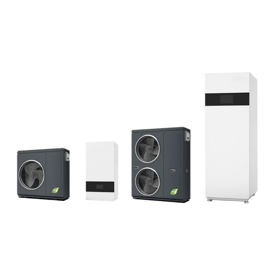
Heat Pump Models:
HS06V-QPNNW
HS08V-QPNNW
HS10V-QPNNW
HS12V-QPNNW
HS15V-QPNNW
Hydraulic Tower Model:
DSK03-QPVTSL200
Hydraulic Station Model:
DSK03-QPVTSG
Before installing operating or carrying out maintenance on this appliance, read and refer
to this manual. Pay particular notice the safety requirements.
Leave this manual with the appliance for future attending engineers to reference.
If this instruction manual is damaged or lost, please contact sales@heatiq.co.nz for a replacement.
This manual and content is subject to copyright (Tradepoint LTD) do not re produce or publish without authorization.
x
e
t
Inverter Heat Pump
R290
Inc,
Hydraulic Station
Operation, Installation & Maintenance manual
For Installers and end Users
New Zealand edition
TradePoint
Tower
Manager
&
-
Distributor
LTD (Heat IQ)
0
Certified and conforms to
EN 14825-2022
EN 12102-1-2022
EN14511-4:2022 Clause 4
EN 14511-3:2022
LVD
EN 60335-1:2012+A15:2021
EN 60335-2-21:2021+A1:2021
EN 60335-2-40 2003+A1:2-021
EN 62233:2008
EMC
EN IEC 55014-1:2021
EN IEC 55014-2:2021
EN IEC 61000-3-2019+A1:2021
EN61000-3-3:2013+A2:2002
Advertisement
Table of Contents

Related Manuals for Heat IQ next HS06V-QPNNW

Summary of Contents for Heat IQ next HS06V-QPNNW
- Page 1 New Zealand edition Distributor TradePoint LTD (Heat IQ) Before installing operating or carrying out maintenance on this appliance, read and refer to this manual. Pay particular notice the safety requirements. Leave this manual with the appliance for future attending engineers to reference.
-
Page 2: Compressor Crankcase Heater
Index Page Description Intended Use 3 – 6 Safety first (All) Integral safety systems Operational principal and configuration format 9 -11 HP specifications Tower and Station Specifications 12-14 HP, Tower and station Exploded diagrams 15-16 Generic system schematics and key component legend 17-18 Safety Zone and clearance requirements 19-21... -
Page 3: Intended Use
Intended use. This HP is of mono-block design. Using outdoor ambient air as its heat source to provide heating and domestic hot water for residential buildings. It is intended exclusively for domestic application. Install outdoors only. Air flow from this appliance must discharge freely to open space and must not be used for any other purpose. -
Page 4: Safety First
Safety first Caution The outdoor HP unit is filled with refrigerant R290 (propane): Mechanical interaction may lead to leaks in the refrigerant circuit. Where leaks of refrigerant occur, there is risk of explosion or asphyxiation. Storage of multiple units Storage must be in accordance with the manufacturer’s instructions, & applicable NZ Legislation. Store in the original packaging in a well-ventilated space at between -25 &... - Page 5 Safety first : R290 refrigerant (propane) is an air displacing, colorless, odorless, flammable gas. Escaping refrigerant can potentially lead to fire or explosion, that may result in serious injury or potential loss of life. When handling moving or disposing of this Heat pump please observe all applicable regulations, standards, directives, ordinances &...
-
Page 6: Power Supply
Safety first : Risk of fire or explosion when removing the refrigerant • Wear suitable personal protective equipment and have a fire Extinguisher present. • Only use tools & equipment that are in good working condition & suitable for R290 refrigerant, •... - Page 7 Safety first: User Guidance Keep the area around the HP clear. Regularly remove debris and leaves that have gathered around and below the HP, and within the evaporator grille. Clear snow from the air inlet and outlet grilles & clear snow that has gathered around the HP.
- Page 8 Integral safety systems Insufficient water flow protection. This function continuously monitors the flow of water through the appliance. It will stop the compressor and backup heater if there is an insufficient flow rate, It will automatically return them back (when present) to operation if the flow rate returns to normal.
-
Page 9: Operating Principal
HP operational principal, configuration, format Operating Principal 1. Low pressure & low temperature liquid refrigerant coming out of expansion valve (4) extracts heat energy from the air via a finned coil heat exchanger (1) and evaporates into gas state. 2. The gas state refrigerant is sucked into compressor (2) and compressed to high pressure and high temperature gas. - Page 10 Heat Pump Specifications Model not available in NZ Specifications / Model HS06V-Q HS08V-Q HS10V-Q HS12V-Q HS15V-Q Heat output at A7/W35℃ 6.19 7.30 6.92 9.87 12.26 Power consumption A7/W35℃ 1.25 1.48 1.45 2.06 2.50 COP at A7/W35℃ 4.95 4.93 4.77 4.79 4.90 Heat output range A7/35℃...
- Page 11 Heat Pump, Compressor oil & filling volume HS06V-QPNNW HAF68 630ml HS08V-QPNNW HAF68 840ml HS10V-QPNNW HAF68 840ml HS12V-QPNNW HAF68 840ml HS15V-QPNNW HAF68 1150ml Hydraulic station specifications Model DSK03-QPVTSG Buffer tank volume Expansion tank volume Expansion tank pre-charged pressure 1.0bar Min operating pressure heating circuit 0.5bar Max operating pressure heating circuit 3bar...
- Page 12 Hydraulic tower specification Model DSK03-QPVTSL200 Duplex stainless steel DHW cylinder material DHW cylinder volume 200L DHW cylinder Max. allowable pressure 6.5bar Max DHW temperature 70℃ Diameter & length of DHW heat exchanger ø28mm x 20m Material of the DHW Heat exchanger SUS316L Surface area of the DHW heat exchanger 1.23m...
- Page 13 Components HS06V-QPNNW / HS08V-QPNNW / HS10V-QPNNW / HS12V-QPNNW / HS12V-DPNNW 1. Finned coil heat exchanger. (Evap, coil) 2. Fan blade. 3. EC Fan motor. 4. De-icing heater. 5. Reactor. 6. Inverter / control board. 7. Plate heat exchanger. 8. 4 way Refrigerant valve. 9.
- Page 14 Components Hydraulic Station 1. Air vent valve. 2. Safety thermostat. 3. Buffer tank. 4. Auxiliary heater. 5. Primary pump. 6. Expansion tank. 7. Three-way valve. 8. Secondary pump. 9. Relay/ A/C contactor. 10. Terminal block. 11. I/O board. 12. Switching power supply. 13.
- Page 15 Components Hydraulic tower 1. Air vent valve. 2. Buffer tank. 3. Safety thermostat. 4. Auxiliary heater. 5. DHW tank. 6. TPR valve. 7. DHW heater and safety thermostat. 8. Drain valve. 9. Expansion tank. 10. Primary pump. 11. Secondary pump. 12.
- Page 16 Generic Systems: Overviews & component legend. F & R Service valves with flexible unions. PG / DRP / Fill point & drain valve Assembly with Gauge. External : Heat Pump Description Station Tower Description Station Tower Primary Circulation pump *Inlet water temperature sensor Integral Integral Integral...
- Page 17 Tower system Buffer Hybrid system optionally with gas boiler Heating system From HP 200L DHW When a boiler is installed in hybrid configuration the HP manages the system controlling efficient use of the boiler. Station system Buffer Hybrid system optionally Heating system with gas boiler...
-
Page 18: Safety Zone
Safety Zone! The refrigerant circuit within The Heat pump contains easily flammable refrigerant in safety group A3 according to ISO 817 and ANSI/ASHRAE Standard 34. A defined safety zone is required in the immediate vicinity of the outdoor unit, in which special requirements apply. R290 refrigerant has a higher density than air. -
Page 19: Installation
Installation: Operational clearances in conjunction with “Safety Zone” Install on a level concrete pad (not connected to the house foundation) with free drainage on all sides. The base must be bigger than the appliance footprint. (Do not install on an unstable surface.) A = 250 mm If operating in temperatures below 0°C for prolonged B = 600 mm... -
Page 20: Condensate Drain
Installation : Heat Pump drainage Condensate Drain Drain outlet adapters are supplied inside the heat pump. plug these into the holes in the appliance drain pan and connect a suitable drain hose (16mm inner diameter) to the adapter. condensate discharges Adapter Condensate collected in the tray is drained via 2 x16mm ID pipes to an appropriate drain or soak away (to avoid blockages or freezing of the drainage pipes the shortest possible run is recommended) -
Page 21: Hydraulic Connections
HP : Cabinet removal Appliance case panels may only be removed by a competent service provider The panels can be removed in the order: Top panel- Plastic cover- Right panel – Front panel - Fan panel. Remove the screws as Remove the screws as shown, remove plastic indicated to remove... -
Page 22: Pipe Sizing
Pipe sizing : Required Primary flow & Return, between HP and indoor unit. Model Multilayer pipe OD Max length elevation HS06V-QPNNW 25mm 35 m 10 m HS08V-QPNNW 32mm 35 m 10 m HS08V-QPNNW 25mm 20 m HS10V-QPNNW 32mm 35 m 10 m HS12V-QPNNW 32mm... -
Page 23: System Expansion Vessel
Installation : System requirements System expansion vessel The expansion vessel for space Heating / Cooling within the Station & Tower is 8L air capacity. Charge pressure is 1 bar. Where the total amount of water in the system is below 160 L this is sufficient. If the total volume is over 160 L, include a secondary expansion tank. - Page 24 Hydraulic station Dimensions & Location Hydraulic station: dimensions : mm Access : remove the screws on the top securing the front panel and push the front panel upwards to open Selecting the Station location • Install indoors or in a garage area that is protected from frost with an environmental temperature between 7°...
- Page 25 Minimum clearances & installation clearances A 100mm B / C 50mm D 200mm E 600mm F 410mm G 340mm H 460mm I 430mm wall bracket dimension hydraulic station holes on the back side Fix the wall bracket to the wall with 4 Ø8 mm bolts, or Tech screws (not supplied) To attach lift up the hydraulic station &...
- Page 26 Hydraulic Tower : Dimensions & Location Remove 3 screws fixing the front panel on the base & push the front panel upward to open. Selecting the Tower location • Install indoors or in a garage area that is protected from frost with an environmental temperature of between 7°...
- Page 27 Tower: hydraulic connections Connect pipework as per the below diagram: ( Valving not shown A 20mm gap is recommended behind the Use the adjustable feet to ensure the Tower. If the Tower is pushed tight to a tower installation is level on both planes. wall introduce 10mm foam packing to the rear to minimise oscillation/noise transfer.
- Page 28 Hydraulic Manager A = 350mm B = 180mm C = 300mm 1 Touch screen 2 I/O Board 3 Switching Power supply Fixings 4 Terminal block 5 A/C Contactor (only for DCH006-D) 11 12 Other Modbus Device D14 and M terminals are used external system control connections in the...
- Page 29 Table A : Manager Connections I/O Board IMPORTANT The control board measures flow rate as per the PWM feedback signal from the circulation pump. the PWM feedback signal function as established by the manufacturer. Only the primary circulation pump as supplied may be used With the Manager module. The circulation pump model can be checked and confirmed within the manufacturer parameters parameter SF35 I/O Board function description...
- Page 30 Volt free input only DO NOT put voltage to this contact. Thermostat Programmable thermostat Heat IQ HIQ436 By example. This control or multiples of it can be added to the same Tuya control App as your HP When SF14 is set to “REMOTE”. Heating On/Off control is taken over by the thermostat. The touch screen can no longer turn the heating On or Off.
- Page 31 Electrical Supply Connection HP Single phase: power supply IMPORTANT: To reduce risk of electric shock during installation. First make water connections, then make electrical connections. If the unit is to be removed first disconnect electrical connections, then disconnect water connections. The appliance (HP) must be installed in accordance with applicable NZ wiring regulations and include…...
-
Page 32: Electrical Diagrams
Electrical Diagrams Station Single phase: Heat Pump and hydraulic DSK03-QPVTSG Wiring connection overview: Tower Single phase: Heat Pump and hydraulic DSK03-QPVTSL200 Wiring connection overview:... - Page 33 Recommended cables and fuse rating for Heat Pumps: Model HS06V HS08V HS10V HS12V-Q HS15V-Q Rated voltage 220-240V/50Hz 1~/N/PE Rated power, Max 2.16 2.86 3.22 4.15 7.10 Rated current ,Max. 12.5 Fuse Power cable with temperature resistance & & indoor/outdoor unit communication 2 core 0.5mm cable (A/B)...
- Page 34 Electrical Accessory Connections DHW reticulation: circulation Pump Connection By introducing pumped domestic hot water reticulation Draw point run off is greatly reduced, hot water is delivered with minimal wait time. 230v Power is supplied via Terminals 3 & 4 If the pump current required exceeds 1A a relay will be required.
- Page 35 Electrical Accessory Connections For connection of your attached system control (potential free switching) Refer to Page 29 Modbus communication connection (10-11) potential free The 10 & 11 potential free contacts on the outdoor unit terminal block, can be connected to a control device for communication via Modbus protocol.
- Page 36 Commissioning and adjustment Note Most Important This HP is equipped with a compressor crankcase heater to heat the compressor oil and evaporate dissolved refrigerant before start-up when outdoor temperature is low. The HP must be, Power on in a standby state for a minimum period before the compressor is run for the first time, …...
- Page 37 Commissioning : System parameter configuration Each installed system will require some parameters set up within the Service engineer or Manufacturer areas. The installing engineer will need to consider the full requirements based on each unique installation. Some parameter adjustments common to every system. We advise the installer to particularly consider the following….
- Page 38 User Guide : Touch screen Interface and operation (Display window & touch pad) A B C D A. Time B. Cooling/heating mode. C. Tap the icon to enter the menu for changing the running mode. D. Running status. :defrost; :off; :on;...
- Page 39 <Confirm> to change between heating & Colling mode User menu Tap icon on the main screen to enter user menu. Heat /Cool – Use to control the heating & cooling temperature setting, and heating & cooling ON/OFF schedule settings. (There is no schedule option where control is via the system) If the heating temperature and or heating schedule needs to be changed, the control must be set to heating mode first.
-
Page 40: Night Mode
Adjusting DHW on/off & Temperature Tap the DHW symbol on the main screen. to adjust the set temperature. DHW Schedule Adjustments; are made as described above for the heating Schedule. Overriding a schedule: When a schedule is set, if DHW or heating on is engaged it will remain ON until the next off time. -
Page 41: Screen Brightness Adjustment
Weather compensation > for enabling or disabling a heating and cooling curve control. See next pages DHW reticulation circulation pump if installed, DHW circulation pump on and off intervals can be set to control circulation of DHW from the cylinder around the reticulation circuit to minimize heat loss and DHW run off. If active the DHW circulation pump will run for the on interval set time - and then remain off for the off interval set time, the cycle repeats. -
Page 42: Weather Compensation
Weather compensation: Users - Seek guidance as required. The heating set point is ST02, described below, and the heating curve factor is ST06,described below: The control temperature for heating & cooling mode has two methods: fixed & changeable temperature. The fixed temperature is a fixed value and directly set by the user at the control. Changeable temperature is determined by values of ST01 cooling setpoint, ST02 heating setpoint, ST06 heating curve factor and the actual outdoor temperature measured by the OT sensor probe. - Page 43 Weather compensation: Users - Seek guidance as required. The temperature of a room with floor heating requires a long time to stabilize. After making any ST02 or ST06 adjustments. Please wait, 24hrs, before making further adjustments. Heating curve settings on the user menu, Adjust ST02 heating setpoint and ST06 heating curve factor, then tap <confirm>, The relative control temperature will be...
-
Page 44: Wifi Configuration
Tuya Smart App setup Download the App by searching “Tuya Smart” in mobile app stores, alternatively for the Android system. scan the following QR code. ▪ Click “Register” read the Privacy Policy. Click “Agree” to enter the registration page. ▪ You can use an email or mobile number to register the account. ▪... - Page 45 Click “Add Device” or “ ” in the top right corner to enter the add device page. There are two ways of adding devices, “Add Manually”- AP networking configuration “Auto Scan” – networking configuration SMARTCONFIG Option1 : Auto scan -Connection to WIFI When using “Auto Scan”, You need to enable and allow access to the location of the phone.
- Page 46 Information I/O input/output data display Press on the main screen, Press Status, The screen displays the unit measured temperature sensors value, digital switch on/off state, components on/off state. Abbreviation description Abbreviation description inlet water temperature Compressor outlet water temperature Circulation pump Ambient temperature Fan motor Suction gas temperature...
- Page 47 Accessing Service & manufacturer Parameters As each system is to some extent unique, the Installer of this appliance will need to adjust some parameter values in order for the appliance operate effectively & efficiently to the system attached. Accessing Parameter settings on the main screen, “service”, Tap “press to enter,...
-
Page 48: Service Parameters
Service Parameters Para. Descriptions De- fault Min. Max. Unit Set Inlet/outlet temp. diff, Cooling :△T of heat pump inlet and outlet to control EV03 ℃ primary pump speed in cooling mode Set Inlet/outlet temp. diff. Heating :△T of heat pump inlet and outlet to control EV04 ℃... - Page 49 Pump mode: Continuous – primary pump will run when heating/cooling switch is turned on. SF220 Continuous Continuous or Regulated Regulated - primary pump ON when compressor ON, OFF when compressor OFF SF221 Current limit enable ON or OFF SF222 ON or OFF Disable force defrost System Back up heater external setup ST07...
- Page 50 System: Working principal Heating Mode, Working Principle: In heating mode, the 3 way valve (VXV) will be open to the heating circuit. Unit On: when BT (buffer tank water temperature.) <T(heating) - ST04 ( temp. diff. heating).(T (heating) is the user set control water temperature in heating mode) Unit Off: BT >T (heating) + 2℃.
- Page 51 System: Working principal Auxiliary electric backup heater control The Auxiliary backup heater can only be activated when all of conditions below are met. 1.) Heating mode is ON & compressor is running at the maximum workable frequency. 2.) The Compressor has run for over 300 second’s. 3.) OT (Ambient temp.) ≤ST07(Back up heater external set point) 4.) BT ≤T (heating) -ST04 (temp.
- Page 52 Service Guide : Operating principals Cooling demand In: RT ( buffer tank water temperature ) On: RT >ST01 (cooling set point) + ST03 ( cooling differential.) Off: RT<ST01-1.5℃ Heating demand In: RT On: RT<T (heating)-ST04(T (heating) is the control water temperature on heating mode) Off: RT>T (heating) + 2℃.
-
Page 53: Water Pump Control
Service Guide : Operating principals Turn on process in heating mode. 1.) Start water pump, check water flow. 2.) if water flow meets requirement and there is heating demand, start fan and compressor. Turn off process in heating mode. 1.) Switch off compressor. 2.) After 5 second’s delay, switch off fan motor. -
Page 54: Crankcase Heater Control
Service Guide Operating principals DHW. The Compressor runs with outlet water PID control with ST21 (Outlet water temperature DHW PID setup, default 70) as the control target In DHW running, when ST ≥ST21 +1℃, the compressor runs at minimum. frequency. 4 way valve control. -
Page 55: Defrosting Control
Service Guide : Operating principals : Defrost Defrosting control. The unit is equipped with hot gas defrosting when the conditions of defrosting are met, 1.) Compressor speed begins to go down. 2.) After compressor speed reduces to 30Hz for 60 seconds, the 4 way valve is switched on, fan motor is switched off and it begins to count defrosting time. -
Page 56: Heating Mode
Service Guide; Operating range The appliance works between a minimum and maximum outdoor temperature. These outdoor temperatures define the application limits for heating mode and cooling mode. If operating outside of the application limits the compressor is switched off. Heating mode The maximum outlet water temperature made by the compressor is subject to the ambient temperature as per this running envelope. - Page 57 EU & UK - Smart Grid : Ready Guide for use N/A for NZ SG READY -Smart Grid This Heat Pump is Smart Grid ready with smart grid certification of the German heat pump association. If there is a SG signal or PV system signal, they can be connected to the unit. This function can only be used in mains networks that support "SG Ready"...
-
Page 58: Important : Safety Guide
IMPORTANT : Safety Guide : Working on this appliance General 1/ Checks to the area : Prior to beginning work on systems containing flammable refrigerants, safety checks are necessary to ensure that the risk of ignition is minimised. For a repair to the refrigerating system, the following precautions shall be complied with. - Page 59 2/Particular attention must be paid to the following to ensure that by working on electrical components, the casing is not altered in such a way that the level of protection is affected. This shall include damage to cables, excessive number of connections, terminals not made to original specification, damage to seals, incorrect fitting of glands, etc.
- Page 60 Decommissioning : Before carrying out this procedure, it is essential that the technician is completely familiar with the equipment and all its detail. It is recommended good practice that all refrigerants are recovered safely. Prior to the task being carried out, an oil and refrigerant sample shall be taken in case analysis is required prior to re-use of reclaimed refrigerant.
-
Page 61: Viewing Alarms
Alarms Alarms are divided into two groups: Auto reset alarms and Manual reset alarms. ▪ Auto reset alarm, the user is not required to acknowledge and reset Auto reset alarms. The unit will automatically restart once the alarm status disappears. ▪... - Page 62 Alarms Auto Reset Alarms The following are codes for auto reset alarms with their meanings. Codes Meaning Low pressure AL01 AL02 High pressure AL03 Low outlet water temperature (ST<AR01 default 5.5) High outlet water temperature (ST>AR03 default 72) AL05 Water flow is inadequate AL17 Primary ump has run at max or minimum output for more than 5 minutes AL79...
- Page 63 Alarms 1.) Low pressure protection (Code: AL01) After starting the compressor, it checks low pressure after AR09 delay. If LPS ≤AR31 for a continual 120 seconds, then the compressor is switched off, 5 seconds later, fan motor is switched off, other parts keep their original state. Alarm code AL01 display on the touch screen.
-
Page 64: Sensor Faults
Alarms 9.) Low evaporation temperature protection (serious) (Code: AL31) If AL20 is triggered over AR16 times within 24 hours, manual reset alarm AL31 is triggered, the compressor is switched off, 5 seconds later, the fan motor is switched off, other parts keep their original state. Alarm code AL31 displays on the touch screen. 10.) Low outlet water temperature protection (Code: AL03) If ST≤AR01 and LPS <... -
Page 65: Maintenance
Periodic servicing: requirements. Note: Annual service is a requirement of the appliance warranty. Heat Pump Maintenance Interval Checking the safety zones integrity Annually Check the alarm log -(action any resulting issues) Annually Carry out a leak check with a suitable detector – (Rectify as Req,) Annually Check the high and low pressure, transducers (replace if required) Annually... - Page 66 Hydraulic Station when included Check the pre-charge pressure of the expansion vessel Annually Check that the 3-way valve can move easily (visually/audibly) Annually Check the electronics boxes, removing any dust Annually Cleaning the buffer tank Annually Hydraulic Tower when included Checking the pre-charge pressure of the expansion vessel Annually Check that the 3 way valve can move easily (visually/audibly)
- Page 67 Periodic service requirements Magnetic de gas & dirt separator, safety relief device within the outdoor unit Unlike the typical position of a magnetic filter (before a heat exchanger) this device is fitted to the flow. It’s primary role is capturing over pressure & discharging escaped refrigerant gas before it can move through the pipeline to enter the property where it could be discharged by system air relief vents.
-
Page 68: Pump Curve
Water Pressure Plots HS04V HS06V HS08V/10V/12V HS15V Pump Curve Primary and secondary pump 25-8... -
Page 69: Temperature And Sensor Resistance Table
Temperature and sensor resistance table Except B5 PT sensor, the other sensors are NTC10K. :10.0 kΩ±1% B25/50:3470K±1% T (℃) Rmin [ KΩ ] Rnom [ KΩ ] Rmax [ KΩ ] 123.5 128.0 132.5 117.0 121.1 125.3 110.8 114.6 118.6 105.0 108.6 112.2... - Page 70 Temperature and sensor resistance table 13.57 13.75 13.93 13.04 13.20 13.37 12.53 12.68 12.83 12.04 12.18 12.32 11.57 11.70 11.84 11.13 11.25 11.37 10.70 10.81 10.93 10.29 10.40 10.50 9.900 10.00 10.10 9.522 9.621 9.721 9.160 9.259 9.359 8.814 8.931 9.012 8.483 8.581...
- Page 71 Temperature and sensor resistance table 2.164 2.218 2.274 2.098 2.152 2.207 2.036 2.088 2.142 1.975 2.027 2.080 1.917 1.976 2.019 1.860 1.910 1.961 1.806 1.855 1.904 1.753 1.801 1.851 1.702 1.749 1.797 1.653 1.699 1.746 1.606 1.651 1.697 1.560 1.604 1.650 1.515 1.599...
- Page 72 Temperature and sensor resistance table These - Only for PT sensor R25=50KΩ±2% B25/50=3950K ±2% T (℃) Rmin [ KΩ ] Rnom [ KΩ ] Rmax [ KΩ ] 441.8 471.5 503.0 417.9 445.5 474.7 395.5 421.1 448.2 374.4 398.2 423.4 354.5 376.7 400.0...
- Page 73 Temperature and sensor resistance table T (℃) Rmin [ KΩ ] Rnom [ KΩ ] Rmax [ KΩ ] 49.00 50.00 51.00 46.87 47.86 48.86 44.83 45.83 46.83 42.90 43.89 44.89 41.06 42.05 43.04 39.31 40.29 41.27 37.64 38.61 39.59 36.05 37.01 37.98...
- Page 74 Temperature and sensor resistance table T (℃) Rmin [ KΩ ] Rnom [ KΩ ] Rmax [ KΩ ] 7.119 7.544 7.991 6.877 7.293 7.731 6.645 7.051 7.480 6.421 6.819 7.238 6.207 6.595 7.005 6.000 6.380 6.781 5.801 6.173 6.565 5.610 5.973 6.357...
-
Page 75: Service Record
Service record. Date Action Primary components of this heat Pump, & Hydraulic units are covered by warranty 5 years for up to * from the date of purchase. Standard cover is 1 year. Cover extends annually up to 5 years.. when the following requirements/ conditions are met... - Page 76 “Thank You for purchasing this quality appliance.” This appliance was proudly supplied & installed by Please leave this manual on site with the appliance end user. Heat t are trademarks of Tradepoint Ltd. This manual is the intellectual property of Tradepoint Ltd Reproduction or publication is not permitted without formal agreement by Tradepoint LTD.
Need help?
Do you have a question about the next HS06V-QPNNW and is the answer not in the manual?
Questions and answers