Table of Contents
Advertisement
Quick Links
Advertisement
Table of Contents

Related Manuals for Deltron Azuri AZI-WE25VF/I

Summary of Contents for Deltron Azuri AZI-WE25VF/I
- Page 1 SERVICE MANUAL...
-
Page 2: Table Of Contents
Service Manua/ Table of Contents P art I : T e ch ni c al lnf o rmati o n ................1. Su mmary ........................2. Sp e c ifi c ati o n s ......................2.1 Specification Sheet ....................3 2.2 Capacity Variation Ratio According to Temperature ........ - Page 3 Service Manua/ 9. Ma i n t enance ......................9.1 E rror Code List ......................9.2 Procedure of Troubleshooting ................. 9.3 Maintenance method for normal malfunction ..........1 0 .1 Indoor U nit ......................1 0 .2 Outdoor Unit ......................11.
-
Page 4: P Art I : T E Ch Ni C Al Lnf O Rmati O N
Service Manua/ Part : Technical lnformation 1. Summary Indoor Unit: AZI-WE25VF/I AZI-WE35VF/I Outdoor Unit: AZI-WE25VF/O AZI-WE35VF/O Remote Controller: YAW1F Technical lnformation • • • •... -
Page 5: Specifications
Service Manua/ 2. Specifications 2.1 Specification Sheet Model AZI-WE25VF AZI-WE35VF Product Code CB4 79004400 CB4 79004300 Rated Voltage 220-240 220-240 Power Rated Frequency Supply Phases Power Supply Mode Outdoor Outdoor Cooling Capacity 2500 3200 2800 Heating Capacity 3400 Cooling Power lnput Heating Power lnput Cooling Power Current Heating Power Current... - Page 6 Service Manua/ Model of Outdoor Unit AZI-WE25VF/O AZI-WE35VF/O Product Code of Outdoor Unit CB385W01000 CB385W01700 ZHUHAI LANDA COMPRESSOR ZHUHAI LANDA COMPRESSOR Compressor Manufacturer/Trademark CO.,LTD CO., LTD K ; ompressor Model FTz-AN075ACBF-A FTz-AN088ACBF-A Compressor Oil FW68DA FW68DA K;ompressor Type Rotary Rotary L.R.A.
-
Page 7: Capacity Variation Ratio According To Temperature
Service Manua/ 2.2 Capacity Variation Ratio According to Temperature Heating Cooling 140 ,---,---,---,---,---,---,---,---,---,----, ----- ___ L ___ L ___ L ___ L ___ L_ � Conditions ·u ° lndoor:DB20 ---. ---1---.---1- Indoor air flow:Super High Conditions ---� ---�---�---�- Pipe length:5m lndoor:DB27'C/WB19"C Indoor air flow:Super High ---L---L---L---L---L---L---L---L---L---... -
Page 8: Outline Dimension Diagram
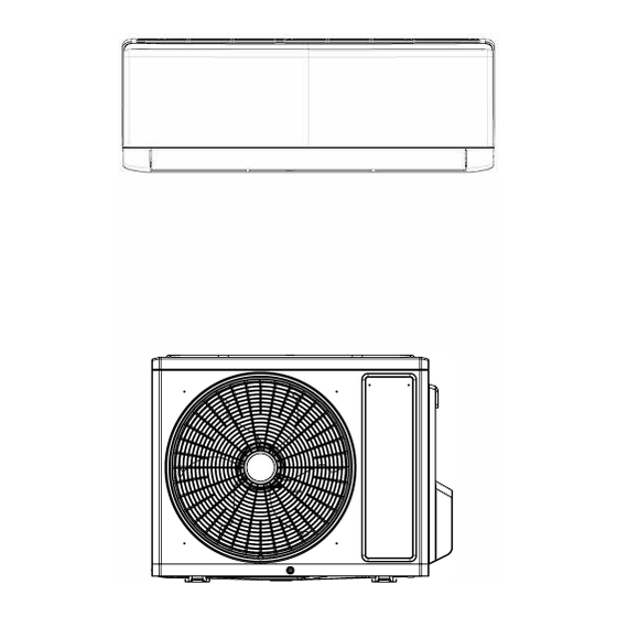
Service Manua/ 3. Outline Dimension Diagram 3.1 Indoor Unit I -- t--� Unit:mm Models • • • Technical lnformation... -
Page 9: Outdoor Unit
Service Manua/ 3.2 Outdoor Unit AZI-WE25VF/O AZI-WE35VF/O � LI') LI') -'� � I• ::=:J c=:-11 �� c=:11 I 1==:=J Unit:mm • ••• • • Technical lnformation... -
Page 10: Refrigerant System Diagram
Service Manua/ 4. Refrigerant System Diagram Cooling and heating model Outdoor unit Indoor unit Gas pipe ______. •---- side Valve • ---- Heat exchanger Compressor ( evaporator) • t Heat exchanger Liquid pipe ----• (condenser) �t side Valve Strainer Capillary Strainer -coOUNG •---- HEATING... -
Page 11: Electrical Part
Service Manua/ 5. Electrical Part 5.1 Wiring Diagram •lnstruction Symbol Symbol Color Symbol Symbol Color Symbol Name White Green Jumper cap Yellow Brown COMP Compressor Blue (-b-) Grounding wire YEGN Yellow/Green Black Violet Orange Note: Jumper cap is used to determine fan speed and the swing angle of horizonta! lover for this model. •... - Page 12 Service Manua/ • Indoor Unit ------------------------------------------, AZI-WE25VF/I AZI-WE35VF/I ROOM TEMP. TEMP. RECEIVER A SOR SE DISPLAY OARD T-SE DISP1 DISP2 � XT YEG I 1-1 1 ,_____--'---' '-------:� I---------'--; PRI NTED CI RCU I T BOARD 1 1 ::::, 1 J UMP COM--OUT �'�...
-
Page 13: Pcb Printed Diagram
Service Manua/ 5.2 PCB Printed Diagram Indoor Unit AZI-WE25VF/I AZI-WE35VF/I • Top view Name Fuse Live wire interface lnterface of health function neutral ..wire(only for the model with this <> function) MARKAREA Neutral wire interface DOOR-C(DRY-C) Fan motor interface of PG JUMP �J17 lnterface of health function live... - Page 14 Service Manua/ Outdoor Unit AZI-WE35VF/O AZI-WE25VF/O • Top view Name Earthing wire Neutral wire, live wire and communication cable 4-wayvalve electric heating belt of chasssis Outdoor fan Electronic expansion valve Overload Temperature sensor T hree-phase terminal of compressor OFAN COM-PC •...
-
Page 15: Function And Control
Service Manua/ 6. Function and Control 6.1 Remote Controller lntroduction Buttons on Remote Controller • On/Off button Mode button Fan button J;,./ T button Swing button Sleep button Temp button Đ Turbo button Đ I Feel button Timer button X-Fan button Light button lcon Display on Remote Controller •14uHl•WM4i---------... - Page 16 Service Manua/ 1. ON/OFF button Press this button to turn on the unit. Press this button again to turn off the unit. 2. MODE button Each time you press this button,a mode is selected in a sequence that goes trom AUTO , COOL, DRY, FAN, and HEAT *, as the following: * Note: Only for models with heating function.
- Page 17 Service Manua/ 11. X-FAN button Press this button in COOL or DRY mode to turn on X-fan function. When this function is started up, indoor fan will still operate at low fan speed for a while after turning off the unit by remote controller.
-
Page 18: Brief Description Of Modes And Functions
Service Manua/ 6.2 Brief Description of Modes and Functions • Indoor Unit 1.Basic function of system (1 )Cooling mode ° (1) Under this mode, fan and swing operates at setting status. Temperature setting range is 16-30 (2) During malfunction of outdoor unit or the unit is stopped because of protection, indoor unit keeps original operation status. (2)Drying mode °... - Page 19 Service Manua/ (8)1 feel control mode After controller received I feel control signal and ambient temperature sent by remote controller, controller will work according to the ambient temperature sent by remote controller. (9)Entry condition for compulsory defrosting function ° ° When turn on the unit under heating ode and set temperature is 16 C (or 16.5 C by remote controller), press "+, -, +, -, +, -"...
- Page 20 Service Manua/ • Outdoor Unit 1. Cooling mode: Working condition and process of cooling mode: CD When Tindoor ambient temperature2!:Tpreset, unit enters into cooling mode. Indoor fan, outdoor fan and compressor start operation. Indoor fan operates according to set fan speed. ®...
- Page 21 Service Manua/ 7.Auto mode Auto mode is determined by controller of IDU. See IDU logic for details. heating ° ° Set temperature is 8 C. Display board of IDU displays 8 C. Under this mode, "Cold air prevention" function is shielded. lf compressor is operating under this mode, fan speed will adjust according to auto fan speed;...
- Page 22 Service Manua/ Part 11 : lnstallation and Maintenance 7. Notes for lnstallation and Maintenance 10. lf the power cord or connection wire is not long enough, Safety Precautions: please get the specialized power cord or connection wire trom the manufacture or distributor. Prohibit prolong the wire lmportant! by yourself.
- Page 23 Service Manua/ Safety Precautions for lnstalling and Relocating the Unit: To ensure safety, please be mindful of the following precautions. � Warnings 1. When installing or relocating the unit, be sure to keep the refrigerant circuit free trom air or substances other than the specified refrigerant.
-
Page 24: Safety Operation Of Flammable Refrigerant
Service Manua/ Safety Operation of Flammable Refrigerant Qualification requirement for installation and maintenance man •AII the work men who are engaging in the refrigeration system should bear the valid certification awarded by the authoritative organization and the qualification for dealing with the refrigeration system recognized by this industry. lf it needs other technician to maintain and repair the appliance, they should be supervised by the person who bears the qualification for using the flammable refrigerant. - Page 25 Service Manua/ Main Tools for lnstallation and Maintenance 1. Level meter, measuring tape 2. Screw driver 3. lmpact drill, drill head, electric drill 4. Electroprobe 5. Universal meter 6. Torque wrench, open-end wrench, inner hexagon spanner 7. Electronic leakage detector 8.
-
Page 26: Lnstallation
Service Manua/ 8. lnstallation 8.1 lnstallation Dimension Diagram Space to the wall S p a c e to t h e o b s tr u c ti o n • • ••• • lnstallation and Maintenance... - Page 27 Service Manua/ lnstallation procedures Start installation Preparation before installation Read the requirements select installation ( Prepare tools) for electric connection Select indoor unit Select outdoor unit installation location installation location lnstall the support of outdoor unit lnstall wall-mounting (select it according to the actual situation) frame, drill wall holes Connect pipes of indoor Fix outdoor unit...
-
Page 28: Lnstallation Parts-Checking
Service Manua/ 8.2 lnstallation Parts-Checking 8.4 Requirements tor electric connection 1. Safety Precaution Name Name (1) Must tonow the electric safety regulations when installing Indoor unit Sealing gum the unit. Outdoor unit Wrapping tape (2) According to the local safety regulations, use qualified Support of outdoor power supply circuit and air switch. - Page 29 Service Manua/ (3) Fix the wall-mounting frame on the wall with tapping screws 5. Connect the Pipe of Indoor Unit and then check if the frame is firmly installed by pulling the (1) Aim the pipe joint at the corresponding bellmouth.(As show frame.
- Page 30 Service Manua/ 7. Connect Wire of Indoor Unit 8. Bind up Pipe (1) Open the panel, remove the screw on the wiring cover and (1) Bind up the connection pipe, power cord and drain hose then take down the cover.(As show in Fig.11) with the band.(As show in Fig.14) (2) Reserve a certain length of drain hose and power cord Panel...
-
Page 31: Lnstallation Of Outdoor Unit
Service Manua/ 8.6 lnstallation of Outdoor unit Refer to the tollowing table tor wrench moment of torce: 1. Fix the Support of Outdoor Unit{Select it according to Piping size (inch) Tightening torque(N-m) the actual installation situation) $1/4 15-20 $3/8 30-40 (1) Select installation location according to the house structure. -
Page 32: Vacuum Pumping And Leak
Service Manua/ 8.8 Check after lnstallation and Test (3) The water outlet cant be placed in water in order to drain smoothly.(As show in Fig.27) operation 1. Check after Installation Check according to the following requirement after finishing The drain hose can't be fluctuant installation. -
Page 33: Maintenance
Service Manua/ 9. Maintenance 9.1 Error Code List Display Method of Outdoor Display Method of Indoor Unit Unit lndicator has 3 kinds of lndicator Display (during display status and during Malfunction blinking, ON O.Ss and OFF Dual-8 NC status Possible Causes blinking, ON O.Ss and OFF Name O.Ss) - Page 34 Service Manua/ Display Method of Outdoor Display Method of Indoor Unit Unit lndicator has 3 kinds of lndicator Display (during display status and during Malfunction blinking, ON 0.5s and OFF Dual-8 NC status Possible Causes blinking, ON 0.5s and OFF Name 0.5s) Code...
- Page 35 Service Manua/ Display Method of Outdoor Display Method of Indoor Unit Unit lndicator has 3 kinds of lndicator Display (during display status and during Malfunction blinking, ON 0.5s and OFF Dual-8 A/C status Possible Causes blinking, ON 0.5s and OFF Name 0.5s) Code...
- Page 36 Service Manua/ Display Method of Outdoor Display Method of Indoor Unit Unit lndicator has 3 kinds of lndicator Display (during display status and during Malfunction blinking, ON 0.5s and OFF Dual-8 A/C status Possible Causes blinking, ON 0.5s and OFF Name 0.5s) Gode...
- Page 37 Service Manua/ Display Method of Outdoor Display Method of Indoor Unit Unit lndicator has 3 kinds of lndicator Display (during display status and during Malfunction blinking, ON 0.5s and OFF Dual-8 A/C status Possible Causes blinking, ON 0.5s and OFF Name 0.5s) Code...
- Page 38 Service Manua/ Display Method of Outdoor Display Method of Indoor Unit Unit lndicator has 3 kinds of lndicator Display (during display status and during Malfunction blinking, ON 0.5s and OFF Dual-8 A/C status Possible Causes blinking, ON 0.5s and OFF Name 0.55) Gode...
- Page 39 Service Manual lf malfunction occurs,corresponding code will display and the unit will resume normal until protection or malfunction disappears. �I Yellow indicator blinks for once Compressor stars (normal) � Defrosting (normal display of indoor uni!) Yellow indicator blinks for twice Anti-freezing protection (normal Yellow indicator blinks for 3 limes display of indoor uni!)
- Page 40 Service Manua/ Analysis or processing of some of the malfunction display: 1. Compressor discharge protection Possible causes: shortage of refrigerant; blockage of air filter; poor ventilation or air flow short pass tor condenser; the system has noncondensing gas (such as air, water etc.); blockage of capillary assy (including filter); leakage inside four-way valve causes incorrect operation;...
-
Page 41: Procedure Of Troubleshooting
Service Manua/ 9.2 Procedure of Troubleshooting 1. Malfunction of Temperature Sensor F1, F2 Main detection points: • 1s the wiring terminal between the temperature sensor and the controller loosened or poorly contacted? • 1s there short circuit due to trip-over of the parts? •... - Page 42 Service Manua/ 2. Malfunction of Blocked Protection of IDU Fan Motor H6 Main detection points: • Smoothlyls the control terminal of PG motor connected tightly? • Smoothlyls the feedback interface of PG motor connected tightly? • The fan motor can't operate? •...
- Page 43 Service Manua/ (3) Malfunction of Protection of Jumper Cap C5 Main detection points: • 1s there jumper cap on the mainboard? • 1s the jumper cap inserted correctly and tightly? • The jumper is broken? • The motor is broken? •...
- Page 44 Service Manua/ 4. Malfunction of Zero-crossing lnspection Circuit Malfunction of the IDU Fan Motor US Main detection points: • lnstant energization afte de-energization while the capacitordischarges slowly? • The zero-cross detectioncircuit of the mainboard is defined abnormal? Malfunction diagnosis process: Start Turn power off for 1 minute,the turn...
- Page 45 Service Manua/ 5. High Temperature and Overload Protection (AP1 below means control board of outdoor unit) ES Start Normal protection, please use ii =>-____:__:=il>fafter improving the outdoor ambient temperature lmprove the radiating environment of unit (clean the heat exchanger and remove surrounding obstacles) Adjust the connection...
- Page 46 Service Manua/ Outdoor unit: (1) Capacitor charge fault (Fault with outdoor unit) (AP1 below refers to the outdoor control panel) Main Check Points: •Use AC voltmeter to check if the voltage between terminal L and N on the wiring board is within 21 0VAC-240VAC. •ls the reactor (L) correctly connected? Is the connection loose or fallen? Is the reactor (L) damaged? Fault diagnosis process: Turn on the unit...
- Page 47 Service Manua/ 2. 1PM protection, phase current overcurrent (the control board as below indicates the control board of outdoor unit) H5/P5 Mainly detect: (1) Compressor COMP terminal (2) voltage of power supply (3) compressor (4) Refrigerant-charging volume (5) air outlet and air inlet of outdoor/indoor unit Troubleshooting: Turn on the unit after energization...
- Page 48 Service Manua/ (3) High temperature and overload protection diagnosis (AP1 hereinafter refers to the control board of the outdoor unit) Mainly detect: •ls outdoor ambient temperature in normal range? •Are the outdoor and indoor fans operating normally? •ls the heat dissipation environment inside and outside the unit good? Fault diagnosis process: Overheat and high temperature protection...
- Page 49 Service Manua/ (4) Start-up failure (following AP1 for outdoor unit control board) Mainly detect: •Whether the compressor wiring is connected correct? •ls compressor broken? •ls time for compressor stopping enough? Fault diagnosis process: Power on the unit Restart it up after ls stop time of the compressor 3 minutes Connect the wires as...
- Page 50 Service Manua/ (5) Out of step diagnosis for the compressor (AP1 hereinafter refers to the control board of the outdoor unit) Mainly detect: •ls the system pressure too high? •ls the input voltage too low? Fault diagnosis process: Out of tep occur Out of step occurs once the operation...
- Page 51 Service Manua/ (6) Overload and air exhaust malfunction diagnosis (following AP1 for outdoor unit control board) Mainly detect: •1s the PMV connected well or not? 1s PMV damaged? •1s refrigerant leaked? Fault diagnosis process: 20 minutes after the Connect the wires correctly Resistances between the first four pins close to the terminal hole and the fifth...
- Page 52 Service Manua/ (7) Communication malfunction: (following AP1 tor outdoor unit control board) Mainly detect: •ls there any damage the indoor unit mainboard communication circuit? 1s communication circuit damaged? •Detect the indoor and outdoor units connection wire and indoor and outdoor units inside wiring is connect well or not, if is there any damage? Fault diagnosis process: Did the equipment operate...
- Page 53 Service Manua/ (8) Malfunction of Overcurrent Protection Main detection points: • 1s the supply voltage unstable with big fluctuation? • 1s the supply voltage too low with overload? • Hardware trouble? Malfunction diagnosis process: Start _.;; :,,.._----=-=-= ---+1 Adjust the supply voltage to maintain ii within normal range Clean the indoor and outdoor heat exchangers and remove the blockage...
-
Page 54: Maintenance Method For Normal Malfunction
Service Manua/ 9.3 Maintenance method for normal malfunction 1. Air Conditioner Cant be Started Up Possible Causes Discriminatinq Method (Air conditioner Status) Troubleshootinq Confirm whether its due to power failure. lf yes, No power supply, or poor wait tor power recovery. lf not, check power �fter energization, operation indicator isnt bright connection tor power plug and the buzzer cant give out sound... - Page 55 Service Manua/ 4. ODU Fan Motor Cant Operate Possible causes Discriminating method (air conditioner status) Troubleshooting Connect wires according to wiring diagram to Wrong wire connection, or poor Check the wiring status according to circuit make sure all wiring terminals are connected connection diagram "irmly...
-
Page 56: Exploded View And Parts List
Service Manua/ 1 O. Exploded View and Parts List 10.1 Indoor Unit ..._____, ..._____, -.._/ / , / ' 20'1 (n�� I ,__ � 2 3 ..__ ..._____, --.___/ ' T he component picture is only for reference; please refer to the actual product. Description Description Front Panel... -
Page 57: 0 .2 Outdoor Unit
Service Manua/ 10.2 Outdoor Unit 33 3 4 AZI-WE25VF/O AZI-WE35VF/O T he component is only for reference;please refer to the actual product. Description Description Coping Compressor and Fittings Supporting Board(Condenser) Chassis Sub-assy 4-WayValve Motor Support Sponge(Condenser) Brushless DC Motor Temperature Sensor Support Axial Flow Fan Condenser Assy Cabinet... -
Page 58: Removal Procedure
Service Manua/ 11. Removal Procedure & Caution: discharge the refrigerant 11.1 Removal Procedure of Indoor Unit completely before removal. Step Procedure 1. Remove filter Panel Open the panel. Loosen the clasp shown in the fig and then pull the left filter and right filer outwards to remove them. - Page 59 Service Manua/ Step Procedure Panel 3. Remove panel Open the front panel; separate the panel rotation shaft trom the groove fixing the front panel and then removes the front panel. Note: The display of some models is fixed on the panel; unscrew the screws fixing the display on the panel before removing the panel.
- Page 60 Service Manua/ Step Procedure Cold plasma generator 6. Remove electric box assy Loosen the connection clasps between Cold plasma generator and electric box, and then remove the cold plasma lectric box generator. Indoor tube Grounding temperature sensor screw G) Cut off the wire binder and pull out the indoor tube temperature sensor.
- Page 61 Service Manua/ Step Procedure 7. Remove evaporator assy Remove 3 screws fixing evaporator assy. Connection pipe clamp At the back of the unit, Loosen the clasp,connection pipe clamp and then remove the connection pipe clamp. Groove First remove the left side of evaporator trom the groove of bottom shell and then remove the right side trom the clasp on the bottom shell.
- Page 62 Service Manua/ Step Procedure 8. Remove motor and cross flow blade Remove 3 screws fixing motor clamp and then remove the motor clamp. Cross flow Remove the at the connection place of Motor cross flow blade and motor; lift the motor and cross flow blade upwards to remove them.
-
Page 63: Removal Procedure Of Outdoor Unit
Service Manua/ 11.2 Removal Procedure of Outdoor Unit AZI-WE25VF/O AZI-WE35VF/O Steps Procedure 1. Before disassembly 2. Remove big handle and valve cover big handle Remove the connection screw fixing the big handle and then remove the valve cover. valve cover 3. - Page 64 Service Manua/ Steps Procedure 4. Remove grille Remove connection screws between the front grille and the front panel. Then remove the grille. grille 5. Remove front panel Remove connection screws connecting the front panel with the chassis and the motor support and then remove the front panel.
- Page 65 Service Manua/ Steps Procedure 8. Remove motor and motor support motor support Remove the tapping screws fixing the motor and disconnect the leading wire insert of the motor. Then remove the motor. Remove the tapping screws fixing the motor support and lift the motor support to motor remove it.
- Page 66 Service Manua/ Steps Procedure 11. Remove compressor Unsolder the welding joint connecting the capillary, valves and the outlet pipe of condenser to remove the capillary. Do not block the capillary with welding slag 4-way valve during unsoldering. Remove the 2 screws fixing the gas valve and unsolder the welding joint between the gas valve and the air-return pipe to �,...
- Page 67 DISTRIBUTOR www.deltron.hr...
Need help?
Do you have a question about the Azuri AZI-WE25VF/I and is the answer not in the manual?
Questions and answers