Table of Contents
Advertisement
Quick Links
Advertisement
Table of Contents

Related Manuals for ZF SCALAR EVO Pulse


Summary of Contents for ZF SCALAR EVO Pulse
- Page 1 Installation Guide SCALAR EVO Pulse...
-
Page 2: Table Of Contents
Best Practices in Installation ......................3 Step 1 - Hardware Components ..................... 4 Hardware Description ........................5 Step 2 - SCALAR EVO Pulse Position ....................6 General Recommendations ........................ 6 Installation without Bracket (Standard Trailer with a Fixed Trailer Bed) ..........6 Alternative Installation without Bracket (Trailer without Fixed Trailer Bed) .......... -
Page 3: Before The Installation
SCALAR EVO Pulse. Liability The installation of SCALAR EVO Pulse can be carried out either by a Certified TEBS Service Partner or by the customer himself (after a ZF-Transics training / demo installation). Contact your service partner in case the TEBS data still need to be activated. -
Page 4: Best Practices In Installation
The assembly of the parts must be done using the accessories provided. ZF-Transics cannot be held responsible for any errors resulting from the use of other materials. ZF-Transics wishes to point out that activities which require welding to the trailer, can cause damage to the electronics of the device. It is imperative that the device is disconnected when carrying out such activities. -
Page 5: Step 1 - Hardware Components
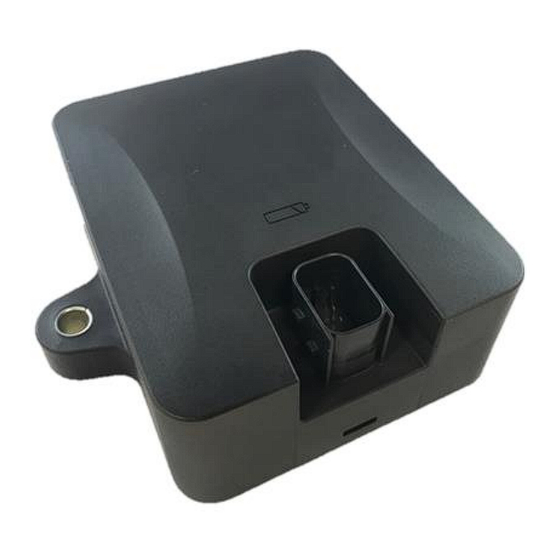
Step 1 - Hardware Components SCALAR EVO Pulse is a trailer tracer unit with an embedded SIM card, GSM antenna, GPS antenna and RF antenna for tire pressure monitoring. It is designed for outside use. It consists of an ECU which can be connected to a trailer’s TEBS system. -
Page 6: Hardware Description
EBS port PIN ASSIGNMENT NOTE: Make sure that the air vent of the SCALAR EVO Pulse unit is always accessible to air. Make sure that nothing can block the air access of the air vent (Do NOT apply glue/tape/silicone along the edges of the unit). -
Page 7: Step 2 - Scalar Evo Pulse Position
Transics technician before deploying it on a large scale. In case the installation includes a TPMS system (with internal sensors cf. p. 38), an installation bracket MUST be used to fix the SCALAR EVO Pulse. If no TPMS system is used, the installation brackets are not required. -
Page 8: Alternative Installation Without Bracket (Trailer Without Fixed Trailer Bed)
Do NOT install the unit on or inside the trailer beams. INCORRECT Do NOT install the unit above other components (e.g. air tanks …). The unit requires a clear view to the bottom. SCALAR EVO Pulse Installation Guide_EN Confidential Page 7 of 47... -
Page 9: Installation With Bracket: Between Axle 2 And 3, Connector Upwards And To The Back Of The Trailer
The general installation instructions to be observed for cables and connectors can be downloaded from: http://inform.wabco-auto.com/intl/drw/9/4490000000.pdf. After connecting all hardware to SCALAR EVO Pulse, ZF-Transics recommends using cable ties to relieve tension from the connectors. SCALAR EVO Pulse Installation Guide_EN... -
Page 10: Fastening Scalar Evo Pulse
Fastening SCALAR EVO Pulse • Install the SCALAR EVO Pulse unit in one of the recommended positions (cf. “General Recommendations” on p.6). • Always verify that sufficient GPS coverage is guaranteed and a good GPS position has been received via https://install.new.wabco-fleet.com/... -
Page 11: Fixing The Bracket To The Trailer
Fixing SCALAR EVO Pulse to the Bracket • Use hexagon head M8 x 1.25, class 8.8 bolts, nuts and washers (not included) treated for the applicable environment to mount the SCALAR EVO Pulse unit on the bracket. • Tighten with a maximum torque of 12.5 Nm. -
Page 12: Step 3 - Connecting The Hardware
Step 3 - Connecting the Hardware Hardware Activation The SCALAR EVO Pulse unit is preactivated and will start sending positions as soon as the unit is connected to an external power source. Connection to SCALAR EVO Pulse All TEBS connection cables use the same type of connector. Always make sure that all connectors are correctly plugged in to ensure a waterproof connection. -
Page 13: Connecting To The Tebs System
In case another TPMS system (such as OptiTire) is connected to the EBS unit, the TPMS data / functionality will be used from that system and not the data from SCALAR EVO Pulse. No matter which configuration (with or without TPMS) you have, ALWAYS install the SCALAR EVO Pulse unit in one of the recommended positions (cf. -
Page 14: Cable Overview
SCALAR EVO Pulse 8946000742 SMARTBOARD II TEBS-E PREMIUM / 4499162530 SUBSYSTEMS STANDARD 8946000012 SCALAR EVO Pulse 8946000012 OPTITIRE TEBS-E PREMIUM / 4499122340 SUBSYSTEMS STANDARD 8946000012 SCALAR EVO Pulse ECAS REMOTE CONTROL UNIT SCALAR EVO Pulse Installation Guide_EN Confidential Page 13 of 47... - Page 15 IMPORTANT When connecting TEBS connection cable “449 916 253 0”, make sure that you connect the wire labeled as “SMARTBOARD” either to the SMARTBOARD or to the SCALAR EVO Pulse unit (see in the images above). TEBS-E STANDARD / PREMIUM...
- Page 16 480 102 03x 0 OR 480 102 06x 0 / 08x 0 (MultiV) Configuration Cable(s) Connections TEBS Port TEBS-E PREMIUM 449 927 020 0 (2.0m) GIO5 SCALAR EVO Pulse 449 927 050 0 (5.0m) 449 927 120 0 (12.0m) SCALAR EVO Pulse Installation Guide_EN Confidential Page 15 of 47...
- Page 17 894 600 001 2 SCALAR EVO Pulse SUBSYSTEMS 894 600 074 2 SMARTBOARD II 449 925 253 0 ELEX ELEX 894 600 001 2 SCALAR EVO Pulse SUBSYSTEMS 894 600 001 2 OPTITIRE SCALAR EVO Pulse Installation Guide_EN Confidential Page 16 of 47...
- Page 18 Gen. 4 “842 ..” Gen. 4 “950 800 ...” Configuration Cable(s) Length Connections TEBS PORT HALDEX Gen. 4 554 051 011 0 5.0 m T-CAN SCALAR EVO Pulse H-CAN SCALAR EVO Pulse Installation Guide_EN Confidential Page 17 of 47...
- Page 19 Configuration Cable(s) Length Connections Power source 449 040 006 0 5.0 m Power source SCALAR EVO Pulse (TPB2) Color Signal White V in Yellow CAN L Green CAN H Brown SCALAR EVO Pulse Installation Guide_EN Confidential Page 18 of 47...
-
Page 20: Wabco Tebs D1 Premium
894 600 001 2 (0.15 m) NOTE: Only basic EBS data (no ODR / DTC) Hardware Connection Connect SCALAR EVO Pulse to the IN/OUT port using the TEBS connection cable. Make sure that the contact pins remain clean and dust-free. -
Page 21: Wabco Tebs E Subsystems
The connector on the TEBS unit remains the same for all cables. TEBS E PREMIUM / STANDARD with SCALAR EVO Pulse TEBS E PREMIUM / STANDARD with SMARTBOARD I (446 192 110 0) and SCALAR EVO Pulse 346 292 001 0... - Page 22 TEBS E PREMIUM / STANDARD with OPTITIRE and SCALAR EVO Pulse 346 292 001 0 TEBS E PREMIUM / STANDARD with ECAS REMOTE CONTROL UNIT and SCALAR EVO Pulse 346 292 001 0 IMPORTANT When connecting TEBS connection cable “449 916 253 0”, make sure that you connect the wire labeled as “SMARTBOARD”...
- Page 23 TEBS E PREMIUM / STANDARD with OPTITIRE, SMARTBOARD II and SCALAR EVO Pulse For this configuration type, the CAN bus termination of the OptiTire ECU must be set to Inactive. “Deactivation of CAN Termination Using Optitire Diagnostics Software” on p.24.
- Page 24 Software Requirements - Ordering the Diagnostic Software Parameter Adaptation If SCALAR EVO Pulse is connected to the subsystem port, telematics must be activated in the TEBS E diagnostics software as the subsystem. 1. In the TEBS E diagnostics software, open the “EBS system parameter settings” menu: In the “Standard functions”...
- Page 25 2. In the “Expert parameter” tab, adjust the setting “Activate CAN termination” according to your configuration type. 3. Press Write to ECU when all modifications have been performed (PIN code needed (cf. “IMPORTANT” on p. 12)). SCALAR EVO Pulse Installation Guide_EN Confidential Page 24 of 47...
-
Page 26: Wabco Tebs E Gio5
449 927 120 0 On TEBS E Premium, you can connect SCALAR EVO Pulse to the modulator GIO5 port via the TEBS GIO5 telematics connection cable (449 927 020 0). SCALAR EVO Pulse Installation Guide_EN Confidential Page 25 of 47... - Page 27 Parameter Adaptation Using TEBS E Diagnostics Software If SCALAR EVO Pulse is connected to the GIO5 slot, telematics must be activated in the TEBS E diagnostics software as a standard function. Requirements TEBS E diagnostics software: Consult Software requirements - Ordering the Diagnostic Software Parameter Adaptation 1.
-
Page 28: Electronic Extension Module (Elex)
ELEX with SCALAR EVO Pulse 346 292 001 0 ELEX with SMARTBOARD and SCALAR EVO Pulse 346 292 001 0 ELEX with SMARTBOARD II and SCALAR EVO Pulse ELEX with SCALAR EVO Pulse and OPTITIRE 346 292 001 0 IMPORTANT When connecting TEBS connection cable “449 925 253 0”, make sure that you connect... -
Page 29: Haldex
TEBS unit. Make sure that the contact pins remain clean and dust-free. Connect SCALAR EVO Pulse to GEN. 1 the DIAG port using the TEBS connection cable. You will first need to remove the blanking plug covering the DIAG port. - Page 30 Gen. 3 Required Cable: Haldex EB+ Gen. 3 DIAGN 449 040 002 0 1. Connect SCALAR EVO Pulse to one of the DIAGN ports (cf. 11 or 12 in picture) using the TEBS connection cable. You will first need to remove the blanking Blanking plugs plug covering the DIAGN port.
- Page 31 In case only H-CAN is active, the telematics unit must be connected to H-CAN. If H-CAN is already occupied, use a ‘Splitter cable’ 844 542 XXX (only to be purchased at Haldex). Please contact your local Haldex service partner to determine the correct connection. SCALAR EVO Pulse Installation Guide_EN Confidential Page 30 of 47...
- Page 32 HCAN HCAN/TCAN • • HCAN/SCAN HCAN/TCAN/SCAN • => connect telematics to T-CAN HCAN/HCAN • HCAN/HCAN/SCAN => connect telematics to H-CAN Please contact your local Haldex service partner for further support. SCALAR EVO Pulse Installation Guide_EN Confidential Page 31 of 47...
- Page 33 The 2 remaining connectors (4) of the Y-splitter cable can now be connected to the connector that was occupying the DIAG port and to the SCALAR EVO Pulse Haldex TEBS connection cable (449 040 002 0). SCALAR EVO Pulse Installation Guide_EN...
- Page 34 1. In the main menu, select Configure, Read, Set up and Program The ECU. 2. Next, click Edit ECU parameters and configuration. 3. Next, click Set up Aux configuration data. SCALAR EVO Pulse Installation Guide_EN Confidential Page 33 of 47...
- Page 35 Next, click Set up Aux configuration and layout. 7. Next, click the Axle load sum button. 8. Confirm the modification by pressing twice. 9. Finally, press Write configuration to the ECU. SCALAR EVO Pulse Installation Guide_EN Confidential Page 34 of 47...
-
Page 36: Knorr
Knorr TEBS connector kit 554 053 011 4 3-way cable junction box 894 600 991 2 Knorr TEBS4 (G1) ES205x In case of a Knorr TEBS unit G1, SCALAR EVO Pulse should be connected to the X2 connector on the TEBS unit. - Page 37 Unplug the existing connector from the TEBS unit and plug in the connector from the TEBS connection cable. Knorr G2.2 ES2090 In case of a Knorr TEBS unit G2.2, SCALAR EVO Pulse should be connected to the IN/OUT connector on the TEBS unit. Available signals: •...
- Page 38 1 x Cable junction box (3 x M16) (894 600 991 2) After connecting all hardware to the SCALAR EVO Pulse unit, you can check the installation (cf. “Step 4 - Checking the Installation” p. 40).
-
Page 39: Connecting To The Internal Sensors
• OptiTire Strap-Mounted Sensors (SMS): Installation on the rim by means of fastening strap. NOTE: SCALAR EVO Pulse is NOT compatible with OptiTire External Sensors (WM2) or any non-WABCO TPMS solution. Connecting to the Internal Sensors (WIS) For selecting the required valve set and further... -
Page 40: Connecting To The Optitire Strap-Mounted Sensors (Sms)
Pulse) (part 000 0) number 960 733 001 0) IMPORTANT Remember to write down the sensor IDs with the corresponding wheel positions when installing the sensors. Use the install form below. SCALAR EVO Pulse Installation Guide_EN Confidential Page 39 of 47... -
Page 41: Step 4 - Checking The Installation
On the Fleet Installer page, select SCALAR EVO Pulse and scan the QR code on the SCALAR EVO Pulse device label (back / top side). Or, enter the 15-digit device serial number (IMEI) manually in... -
Page 42: Installation Wizard
Trailer manufacturer • Association License plate Customer • Axles and tires Number of axles Tire type: Single / Twin Axle brand Axle model Tire brand Tire model Press Next to continue. SCALAR EVO Pulse Installation Guide_EN Confidential Page 41 of 47... -
Page 43: Battery Status
In case the EBS status is not OK, verify all cable connections. • Axle load • Mileage / Odometer • Speed • EBS brand / model • History: last received valid status Press Next to continue. SCALAR EVO Pulse Installation Guide_EN Confidential Page 42 of 47... -
Page 44: Gps Status
Set the tire type: single / twin axle 3. Add the sensor IDs per location by clicking the tire location in the image: Example: A1L1 (Axle 1, 1 tire on the left) SCALAR EVO Pulse Installation Guide_EN Confidential Page 43 of 47... -
Page 45: Send Installation Report
Enter the required parameters: • Email address NOTE: You can send the report to multiple email addresses. • Installer • Workshop • Comment Press Send to complete the process. SCALAR EVO Pulse Installation Guide_EN Confidential Page 44 of 47... -
Page 46: Health Overview
In case the battery status is not OK, verify all cable connections. • GPS status: OK / Not OK In case the GPS status is not OK, make sure that the position of SCALAR EVO Pulse meets the requirements (cf. “Step 2 - SCALAR EVO Pulse Position” on p.6). •... -
Page 47: Contact Information
Furthermore, ZF | Transics does not warrant, guarantee or make any representations regarding the use, or the results of the use of the software or the information contained herein. ZF | Transics shall not be liable for any direct, indirect, consequential or incidental damages arising out of the use or inability to use the software or the information contained herein.
Need help?
Do you have a question about the SCALAR EVO Pulse and is the answer not in the manual?
Questions and answers
How do I mount the wheel sensors for the Scalar Evo pulse unit
To mount the wheel sensors for the ZF SCALAR EVO Pulse unit:
1. Sensor Type: Choose the correct sensor model (WIS or SMS). SCALAR EVO Pulse is not compatible with OptiTire External Sensors (WM2) or any non-WABCO TPMS solutions.
2. Sensor Placement:
- Set the number of axles (1–6).
- Set the tire type (single or twin axle).
- Assign sensor IDs to each tire location (e.g., A1L1 for Axle 1, left tire 1).
3. Sensor Installation:
- Use the TPMS manager tool (part number 300 200 001 0) to activate the sensor and read its ID.
- Enter the sensor ID manually or select it from detected sensors.
- Repeat for each tire.
4. Documentation:
- Record each sensor ID with its corresponding wheel position.
- Send an installation report via email with installer details and comments, if needed.
This answer is automatically generated