Table of Contents
Advertisement
Quick Links
Advertisement
Chapters
Table of Contents
Troubleshooting

Related Manuals for MOOVAIR DUB12HIFU230X5A

Summary of Contents for MOOVAIR DUB12HIFU230X5A
- Page 1 SERVICE MANUAL MOOVAIR MODEL FACTORY CODE PRODUCT CODE DUB12HIFU230X5A MFA2U-12HRFN1-MW5W 22022611000207 DMA12HOS25230E8 MOX230-12HFN1-MV5W 22022016016322 DMA12HOS28230E8 MOX330-12HFN1-MW5W 22022016016220 SRM_M_UNIHIF_0_XXXX_2207XX moovair.ca...
- Page 2 SM_NEW CONSOLE(GA)_R410A_3D INV_US1_NA_2207 CONSOLE INVERTER SERIES SERVICE MANUAL...
- Page 4 Table of Contents §. Safety Precautions Precautions Information servicing §. Model Reference & External Appearance Model Reference External Appearance §. Indoor Unit Indoor Unit - New Console Type §. Outdoor Unit Dimensional Drawings Service Space Capacity Correction Factor for Height Difference Noise Criterion Curves Refrigerant Cycle Diagrams Electrical Wiring Diagrams...
- Page 5 Table of Contents §. Troubleshooting Safety Caution General Troubleshooting Information Inquiry Error Diagnosis and Troubleshooting Without Error Code Quick Maintenance by Error Code Troubleshooting by Error Code Check Procedures §. Indoor Unit Disassembly Indoor Unit - New Console Type §. Outdoor Unit Disassembly Appendix Temperature Sensor Resistance Value Table for T1,T2,T3 and T4 (°C –...
-
Page 7: Safety Precautions
Safety Precautions Contents Precautions ......................2 Information servicing(For flammable materials) ..........3... -
Page 8: Operation And Maintenance
1. Precautions CAUTION • To prevent personal injury, or property or unit damage, While unpacking be careful of sharp edges around adhere to all precautionary measures and instructions the unit as well as the edges of the fins on the con- denser and evaporator. - Page 9 2. Information servicing(For to the surrounding space. Prior to work taking place, the area around the equipment is to be surveyed to make sure flammable materials) that there are no flammable hazards or ignition risks. NO SMOKING signs shall be displayed. Checks to the area Ventilated area •...
- Page 10 • that capacitors are discharged: this shall be done in a shall also take into account the effects of aging or safe manner to avoid possibility of sparking continual vibration from sources such as compressors or fans. • that there no live electrical components and wiring are exposed while charging, recovering or purging the 2.13 Detection of flammable refrigerants system;...
-
Page 11: Charging Procedures
• The refrigerant charge shall be recovered into the • Before attempting the procedure ensure that: correct recovery cylinders. The system shall be flushed • mechanical handling equipment is available, if with OFN to render the unit safe. This process may required, for handling refrigerant cylinders;... - Page 12 • Empty recovery cylinders are evacuated and, if are unaware of the procedure taking place possible, cooled before recovery occurs. • The hose must be of sufficient length and diameter • The recovery equipment shall be in good working such that it will extend to at least 3 m beyond the order with a set of instructions concerning the outside of the building equipment that is at hand and shall be suitable for the...
-
Page 13: Model Reference
Model Reference Contents Model Reference ....................2 External Appearance .....................3... - Page 14 1. Model Reference Refer to the following table to determine the specific indoor and outdoor unit model number of your purchased equipment. Capacity Indoor Unit Model Universal Outdoor Unit Model Power Supply (Btu/h) MOX230-12HFN1-MV5W MOX330-12HFN1-MW5W 9k Hyper Heat MFA2U-12HRFN1-MW5W MOX230-12HFN1-MV5W 1Phase, Console 12k Hyper...
-
Page 15: External Appearance
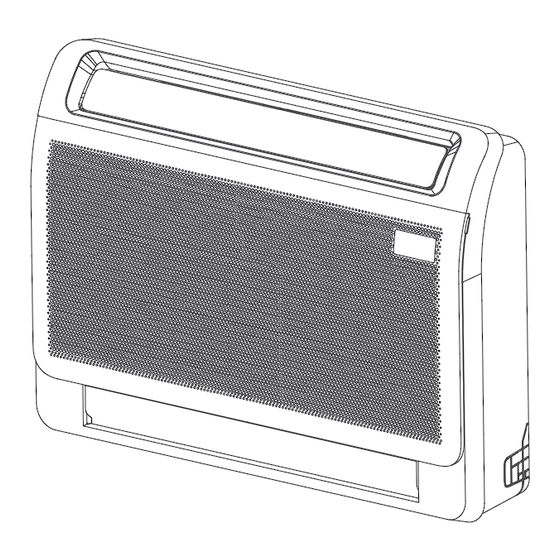
2. External Appearance Indoor Unit New Console Outdoor Unit Single Fan Outdoor Unit Model Reference... -
Page 16: Table Of Contents
Indoor Unit-New Console Contents Feature........................2 Dimensional Drawings ..................4 Part names ......................5 Service Place ......................5 Accessories ......................6 Air Velocity and Temperature Distributions ............8 Noise Criterion Curves ..................10 Electrical Characteristics ..................11 Electrical Wiring Diagrams ..................11... -
Page 17: Feature
1. Feature An Elegant And Compact Design • The look of newly-upgraded console unit features flowing lines that is aesthetic enough. • Its unobtrusive design can easily fit into most interiors with different decorating-schemes. • The width of the machine has been reduced by 10mm, taking less space. A Perfect Choice For New Buildings And Renovation Projects •... -
Page 18: Air Quality
• Wide Airflow & Constant Comfort-Dual air outlets satisfy both cooling and heating needs in different seasons and allows a quick comfort of the room. *Compared to last generation console unit Air Quality We care your indoor air quality from many perspectives •... -
Page 19: Dimensional Drawings
2. Dimensional Drawings IDU-New Console 4... -
Page 20: Part Names
3. Part names Air flow louver (at air outlet) Display panel Air inlet (with air filter in it) Refrigerant connecting pipe Air flow louver (at air outlet) Drain hose 4. Service Place ≥100mm ≥1000mm IDU-New Console 5... -
Page 21: Accessories
5. Accessories The air conditioning system comes with the following accessories. Use all of the installation parts and accessories to in- stall the air conditioner. Improper installation may result in water leakage, electrical shock and fire, or equipment failure. Name Shape Quantity Remote controller... - Page 22 Transfer connector(Φ12.7-Φ15.9)/(Φ0.5in-Φ0.63in)(Packed with the indoor unit) NOTE: Pipe size may differ from appliance to appliance. To meet different pipe size requirements, sometimes (on some models) the pipe connections need a transfer connector installed on the outdoor unit . Transfer connector(Φ6.35-Φ9.52)/(Φ0.25in-Φ0.37in)(Packed with the indoor unit) NOTE: Pipe size may differ from appliance to appliance.
-
Page 23: Air Velocity And Temperature Distributions
6. Air Velocity and Temperature Distributions Discharge Angle 70°(Upper)/ 0°(Lower) Cooling airflow velocity distributions Cooling temperature distributions IDU-New Console 8... - Page 24 Discharge Angle 20°(Upper)/ 0°(Lower) Heating airflow velocity distributions Heating temperature distributions IDU-New Console 9...
-
Page 25: Noise Criterion Curves
8. Noise Criterion Curves 1m/3.28ft 1.5m/4.92ft Notes: -Sound measured at 1m/3.28 away from the unit and 1.5m/4.92ft away from the ground. -Data is valid at free field condition -Data is valid at nominal operation condition -Reference acoustic pressure OdB = 20µPa -Sound level will vary depending on a range of factors such as the construction -(acoustic absorption coefficient) of particular room in which the equipment is installed. -
Page 26: Electrical Characteristics
9. Electrical Characteristics 9k/12k hyper Capacity (Btu/h) 9k/12k 18k hyper Heat Heat Phase Power (Outdoor) Frequency And Volt 208/230V,60Hz Indoor unit(A) Max Fuse Outdoor unit(A) Line quantity Outdoor Unit Line 14/2.5mm² 14/2.5mm² 14/2.5mm² 12/4.0mm² Power Wire diameter(AWG) Line quantity Outdoor-indoor Line 16/1.5mm 16/1.5mm... -
Page 28: Outdoor Unit
Outdoor Unit Contents Dimensional Drawings ..................2 Service Place ......................18 Capacity Correction Factor for Height Difference ..........19 Noise Criterion Curves ..................25 Refrigerant Cycle Diagrams ................27 Electrical Wiring Diagrams ..................29... -
Page 29: Dimensional Drawings
1. Dimensional Drawings Please check the corresponding dimensional drawing according to the panel plate. ODU Model Panel Plate MOX230-12HFN1-MV5W X230 MOX330-12HFN1-MW5W X330 MOX430-18HFN1-MU0W X430 MOX430-17HFN1-MT0W X430 Outdoor Unit 2... - Page 30 Panel Plate X230 (Rounded grille 1) Outdoor Unit 3...
- Page 31 Panel Plate X230 (Rounded grille 2) Outdoor Unit 4...
- Page 32 Panel Plate X230(Square grille) Outdoor Unit 5...
- Page 33 X330(Rounded grille 1) Panel Plate Outdoor Unit 6...
- Page 34 X330(Rounded grille 2) Panel Plate Outdoor Unit 7...
- Page 35 X330(Square grille) Panel Plate Outdoor Unit 8...
- Page 36 X430(Rounded grille 1) Panel Plate Outdoor Unit 9...
- Page 37 X430(Rounded grille 2) Panel Plate Outdoor Unit 10...
- Page 38 X430(Square grille) Panel Plate Outdoor Unit 11...
- Page 39 Panel Plate D30(Rounded grille 1) Outdoor Unit 12...
- Page 40 Panel Plate D30(Rounded grille 2) Outdoor Unit 13...
- Page 41 Panel Plate D30(Square grille) Outdoor Unit 14...
- Page 42 Panel Plate X630(Square grille) Outdoor Unit 15...
- Page 43 Panel Plate E30(Square grille) Outdoor Unit 16...
- Page 44 Panel Plate E30(Rounded grille 1) Outdoor Unit 17...
- Page 45 Panel Plate E30(Rounded grille 2) Outdoor Unit 18...
-
Page 46: Service Place
2. Service Place Outdoor Unit 19... -
Page 47: Capacity Correction Factor For Height Difference
3. Capacity Correction Factor for Height Difference Capacity(Btu/h) 6k~9k Pipe Length (m/ft) Cooling 7.5/24.6 10/32.8 20/65.6 25/82 10/32.8 0.969 0.936 0.920 Indoor Upper than Outdoor 5/16.4 0.995 0.979 0.946 0.929 Height difference 1.000 0.984 0.951 0.934 H (m) -5/-16.4 1.000 0.984 0.951 0.934... - Page 48 Capacity(Btu/h) Pipe Length (m/ft) Heating 7.5/24.6 10/32.8 20/65.6 30/98.4 20/65.6 0.987 0.978 Indoor Upper 10/32.8 0.996 0.987 0.978 than Outdoor 5/16.4 1.000 0.996 0.987 0.978 Height difference 1.000 0.996 0.987 0.978 H (m) -5/-16.4 0.992 0.988 0.979 0.970 Outdoor Upper -10/-32.8 0.980 0.971...
- Page 49 Capacity Pipe Length (m/ft) (Btu/h) Cooling 7.5/24.6 10/32.8 20/65.6 30/98.4 40/131.2 50/164 25/82 0.891 0.862 0.832 20/65.6 0.930 0.900 0.871 0.841 Indoor Upper than Outdoor 10/32.8 0.970 0.940 0.910 0.879 0.849 Height 5/16.4 0.995 0.980 0.949 0.919 0.888 0.858 difference 1.000 0.985 0.954...
- Page 50 Capacity Pipe Length (m/ft) (Btu/h) Cooling 7.5/24.6 15/49.2 25/82 35/114.8 50/164 65/213.3 30/98.4 0.889 0.850 0.812 20/65.6 0.924 0.898 0.859 0.820 Indoor Upper than Outdoor 10/32.8 0.959 0.933 0.907 0.868 0.828 5/16.4 0.995 0.969 0.942 0.916 0.876 0.837 Height difference 1.000 0.974 0.947...
- Page 51 Capacity Pipe Length (m/ft) (Btu/h) Cooling 7.5/24.6 15/49.2 25/82 35/114.8 50/164 65/213.3 30/98.4 0.884 0.843 0.802 20/65.6 0.920 0.893 0.852 0.810 Indoor Upper than Outdoor 10/32.8 0.957 0.930 0.902 0.860 0.819 5/16.4 0.995 0.967 0.939 0.911 0.869 0.827 Height difference 1.000 0.972 0.944...
- Page 52 Capacity Pipe Length (m/ft) (Btu/h) Cooling 7.5/24.6 15/49.2 25/82 35/114.8 50/164 65/213.3 30/98.4 0.870 0.823 0.775 20/65.6 0.911 0.879 0.831 0.783 Indoor Upper than Outdoor 10/32.8 0.953 0.920 0.888 0.840 0.791 5/16.4 0.995 0.962 0.930 0.897 0.848 0.799 Height difference 1.000 0.967 0.934...
-
Page 53: Noise Criterion Curves
4. Noise Criterion Curves Note: H= 0.5 × height of outdoor unit Notes: -Sound measured at 1.0m away from the center of the unit. -Data is valid at free field condition -Data is valid at nominal operation condition -Reference acoustic pressure OdB=20µPa -Sound level will vary depending on arrange off actors such as the construction (acoustic absorption coefficient) of particular room in which the equipment is installed. - Page 54 MOX230-12HFN1-MV5W MOX330-12HFN1-MW5W MOX430-17HFN1-MT0W MOX430-18HFN1-MU0W Outdoor Unit 26...
-
Page 55: Refrigerant Cycle Diagrams
5. Refrigerant Cycle Diagrams Pipe Size (Diameter:ø) Piping length (m/ft) Elevation (m/ft) mm(inch) Model Additional Refrigerant Liquid Rated Max. Rated Max. MOX230-12HFN1-MV5W 12.7(1/2) 6.35(1/4) 7.5/24.6 25/82 10/32.8 15g/m (0.16oz/ft) MOX330-12HFN1-MW5W Outdoor Unit 27... - Page 56 Pipe Size (Diameter:ø) Piping length (m/ft) Elevation (m/ft) mm(inch) Model Additional Refrigerant Liquid Rated Max. Rated Max. MOX430-18HFN1-MU0W 12.7(1/2) 6.35(1/4) 7.5/24.6 30/98.4 20/65.6 15g/m (0.16oz/ft) MOX430-17HFN1-MT0W Outdoor Unit 28...
-
Page 57: Electrical Wiring Diagrams
Electrical Wiring Diagrams ODU Model ODU Wiring Diagram MOX230-12HFN1-MV5W 16022000035853 MOX330-12HFN1-MW5W MOX430-18HFN1-MU0W 16022000035849 MOX430-17HFN1-MT0W ODU Model ODU Main Printed Circuit Board MOX230-12HFN1-MV5W 17122000048121 MOX330-12HFN1-MW5W MOX430-18HFN1-MU0W 17122000048066 MOX430-17HFN1-MT0W 17122000041117 Outdoor Unit 29... - Page 60 Outdoor unit printed circuit board diagram: 17122000044714, 17122000048121,17122000046453...
- Page 61 Name Meaning Earth: connect to Ground N_in: connect to N-line (208-230V AC input) CN1A L_in: connect to L-line (208-230V AC input) CN16 S: connect to indoor unit communication HEAT1 CN17 connect to compressor heater, 208-230V AC when is ON 4-WAY CN60 connect to 4 way valve, 208-230V AC when is ON.
- Page 62 Earth N-IN L-IN CN17 AC-FAN 4-WAY HEAT2 CN 60 R109 C515 CN 6 IC4 04 C 40 8 R403 E502 CN4 14 DC-FAN CN1 9 R4 04 C 517 C5 19 CN 18 R Y5 L2 01 IC401 E504 CN23 R8 02 R 804 C 40 2...
- Page 63 Name Meaning Earth: connect to Ground Power Supply N_in: connect to N-line (208-230V AC input) L_in: connect to L-line (208-230V AC input) S: connect to indoor unit communication 4-WAY CN60 connect to 4 way valve, 208-230V AC when is ON. AC-FAN connect to AC fan HEAT2...
- Page 64 Outdoor unit printed circuit board diagram: 17122000041117, 17122000034170...
- Page 65 Name Meaning Earth: connect to Ground Power Supply N_in: connect to N-line (208-230V AC input) L_in: connect to L-line (208-230V AC input) S: connect to indoor unit communication 4-WAY CN60 connect to 4 way valve, 208-230V AC when is ON. HEAT1 CN16 connect to compressor heater, 208-230V AC when is ON...
-
Page 66: Installation
Installation Contents Installation Overview Location Selection Indoor Unit Installation Outdoor Unit Installation Drainage Pipe Installation Refrigerant Pipe Installation Vacuum Drying and Leakage Checking Additional Refrigerant Charge Engineering of Insulation Engineering of Electrical Wiring Test Operation... -
Page 67: Installation Overview
1. Installation Overview Indoor Unit Indoor Unit Install the indoor unit Install the outdoor unit Install the drainpipe Evacuate the refrigeration system Connect the wires Connect the refrigerant pipes Install the panel Perform a test run (only for cassette type) ... -
Page 68: Location Selection
DO NOT install the rows of series like following figure. 2. Location selection 2.1 Unit location selection can refer to installation manual. 2.2 DO NOT install the unit in the following locations: • Where oil drilling or fracking is taking place. •... -
Page 69: Installing The Main Body
3. Indoor Unit Installation(New NOTE: It is recommended to fx it on the wall according to the hanging hole indicated by the arrow on the mounting Console) plate. Mounting plate must be installed horizontally. 3.1 Service space for indoor unit Mounting plate ≥100mm Tapping... -
Page 70: Refrigerant Pipe
open the piping cover plate. Two buckles Refrigerant pipe Drain-pipe Power cord NOTE: In order to drain smoothly, the position of the drain pipe must refer to the above figure when discharging the right pipe. • Installation with skirting line 2. -
Page 71: Outdoor Unit Installation
4. Outdoor unit installation 2. Connect a drain hose extension (not included) to the drain joint to redirect water from the unit during heating 4.1 Service space for outdoor unit mode. 4.3 Bolt pitch Panel Plate Unit 4.2 Install drain joint(Heat pump unit only) inch 11.93 17.80... - Page 72 4.4 Install Outdoor Unit Fix the outdoor unit with anchor bolts(M10) >60cm / 23.6” Fix with bolts Caution Since the gravity center of the unit is not at its physical center, so please be careful when lifting it with a sling. Never hold the inlet of the outdoor unit to prevent it from deforming.
-
Page 73: Drainage Pipe Installation
For Vertical drainage pipe (The following table is for 5. Drainage Pipe Installation reference) Install the drainage pipe as shown below and take Reference measures against condensation. Improperly installation Allowable value of inner could lead to leakage and eventually wet furniture and maximum water Remark pipe... - Page 74 should design a blowhole at the highest point of main pipe to ensure the condensate water discharge smoothly. • The air outlet shall face down to prevent dirt enter- ing pipe. • Each indoor unit of the system should be installed it. •...
-
Page 75: Refrigerant Pipe Installation
Indoor unit/ 6. Refrigerant Pipe Installation Outdoor unit 6.1 Recommended copper pipe thickness Pipe Diameter Thickness(mm/inch) 1/4" (6.35) 0.6/0.024 3/8" (9.52) 0.7/0.028 1/2" (12.7) 0.75/0.03 6m/20ft (<36000Btu/h unit) 10m/32.8ft (≥36000Btu/h unit) 5/8" (15.9) 0.75/0.03 Indoor unit/ 3/4" (19) 0.8/0.031 Outdoor unit 7/8"... -
Page 76: Vacuum Drying And Leakage Checking
7. Vacuum Drying and Leakage Pipe diameter Flare dimension A (mm/inch) Flare shape Checking (inch(mm)) 1/4" (6.35) 8.4/0.33 8.7/0.34 7.1 Purpose of vacuum drying • Eliminating moisture in system to prevent the phe- 3/8" (9.52) 13.2/0.52 13.5/0.53 90 ° ± 4 nomena of ice-blockage and copper oxidation. -
Page 77: Additional Refrigerant Charge
4. Rain water might penetrate into pipeline during 8. Additional Refrigerant Charge construction. • After the vacuum drying process is carried out, the additional refrigerant charge process need to be performed. Procedures of special vacuum drying are as follows: • The outdoor unit is factory charged with refrigerant. -
Page 78: Engineering Of Insulation
• 9 . Engineering of Insulation Be sure not bind the insulation material over-tight, it may extrude out the air in the material to cause bad 9.1 Insulation of refrigerant pipe insulation and cause easy aging of the material. 9.2 Insulation of drainage pipe 1. -
Page 79: Test Operation
Engineering of Electrical Wring 11. Test Operation 1. Highlights of electrical wiring installation 1. The test operation must be carried • out after the entire installation has been All field wiring construction should be finished by qualified electrician. completed. • Air conditioning equipment should be grounded ac- 2. - Page 80 b. Make sure there is no vibration or abnormal noise using the drainage plug, and put the test cap back to the during operation. original place. c. Ensure the wind, noise, and water generated by the unit CAUTION: do not disturb your neighbors or pose a safety hazard. The drainage plug at the bottom of the unit body is used to discharge accumulated water from the drain pan when 4.
-
Page 81: Maintenance
Maintenance Contents First Time Installation Check .................2 Refrigerant Recharge ....................4 Re-Installation .......................5 Indoor Unit ....................5 Outdoor Unit ....................7... -
Page 82: First Time Installation Check
1. First Time Installation Check Air and moisture trapped in the refrigerant system affects To prevent air and moisture from affecting the air the performance of the air conditioner by: conditioner’s performance, the indoor unit, as well as the pipes between the indoor and outdoor unit, must be be •... - Page 83 Procedure: • If the pressure successfully reaches -0.1 MPa Tighten the flare nuts of the indoor and outdoor (14.5 Psi), fully close the Handle Lo valve, then units, and confirm that both the 2- and 3-way valves cease vacuum pump operations. are closed.
-
Page 84: Refrigerant Recharge
2. Refrigerant Recharge mA A Procedure: Close both 2- and 3-way valves. 3-way valves. Slightly connect the Handle Lo charge hose to the Operate the air conditioner in cooling mode to charge 3-way service port. the system with liquid refrigerant. Connect the charge hose to the valve at the bottom When the electronic scale displays the correct of the cylinder. -
Page 85: Re-Installation
3. Re-Installation Indoor Unit Collecting the refrigerant into the outdoor unit Procedure: Confirm that the 2- and 3-way valves are opened. Close the 3-way valve so that the gauge rests between 0.3 MPa (43.5 Psi) and 0.5 MPa (72.5 Psi). Connect the charge hose with the push pin of Handle Lo to the 3-way valve’s gas service port. - Page 86 Air purging with vacuum pump Procedure: Tighten the flare nuts of the indoor and outdoor • If the pressure successfully reaches -0.1 MPa (14.5 Psi), fully close the Handle Lo valve, then units, and confirm that both the 2- and 3-way valves cease vacuum pump operations.
-
Page 87: Outdoor Unit
Outdoor Unit Evacuation for the whole system Procedure: Wait for 5 minutes then check whether the gauge Confirm that the 2- and 3-way valves are opened. needle moves after turning off the vacuum pump. If Connect the vacuum pump to the 3-way valve’s the gauge needle moves backward, check whether service port. - Page 88 Refrigerant charging mA A Procedure: Close both 2- and 3-way valves. Fully open the Handle Lo manifold valve, 2- and 3-way valves. Slightly connect the Handle Lo charge hose to the 3-way service port. Operate the air conditioner in cooling mode to charge the system with liquid refrigerant.
- Page 89 Product Features Contents Display Function ....................2 Safety Features ......................5 Basic Functions .......................6 Table ......................6 Abbreviation ....................7 Fan Mode ......................7 Cooling Mode ....................7 Heating Mode(Heat Pump Units) ..............8 Auto-mode ....................9 Drying Mode ....................10 Forced Operation Function ................10 Timer Function ....................10 3.10 ECO Function ....................10 3.11 Auto-Restart Function ..................10 3.12 Drain Pump Control ..................10 Optional Functions ....................11...
-
Page 90: Display Function
1. Display Function Floor Ceiling Type MANUAL MANUAL MANUAL OPERATION OPERATION OPERATION TIMER TIMER TIMER PRE-DEF Infrared receiver (pre-heating/defrost) Timer indicator DEF./FAN DEF./FAN DEF./FAN ALARM ALARM ALARM indicator MANUAL Operation indicator Manual button Alarm indicator LED display Display 1 Display 2 PRE-DEF (pre-heating/defrost) Operation indicator... - Page 91 New 4-way Cassette Type &New Compact Cassette Type Electric heating indicator Alarm indicator ( some models) When wireless control LED display feature is activated ( some models) Timer PRE-DEF indicator indicator (pre-heating/defrost) Operation indicator 1-way Cassette Type “ ” when Electric heating feature is activated (Not available for this unit). “...
- Page 92 Compact Cassette Type Console Type Infrared receiver Operation indicator Timer indicator PRE-DEF (pre-heating/defrost) indicator Manual button Display 1 Infrared receiver Operation indicator Manual button Display 2 Product Features...
- Page 93 New Console Type Display Function ECO function (available on select units only) When Wireless Control feature is activated (some units) Temperature value Temperature Timer ON is set. (3s) Activation of Swing, Boost, Silence or UV-C lamp Timer OFF is set. (3s) Cancellation of Swing, Boost, Silence or UV-C lamp Defrost...
-
Page 94: Safety Features
2. Safety Features Compressor three-minute delay at restart Compressor functions are delayed for up to ten seconds upon the first startup of the unit, and are delayed for up to three minutes upon subsequent unit restarts. Automatic shutoff based on discharge temperature If the compressor discharge temperature exceeds a certain level for nine seconds, the compressor ceases operation. -
Page 95: Basic Functions
3. Basic Functions Table Cooling Mode&Heating mode Heating Mode Functions Auto mode Defrosting Anti-cold Air Outdoor Fan Control Mode Function Case 1: Cases Compressor Case 2:T4 Case 1 Case 2 Case 1 Case 2 Case 1 Case 2 Case 3 Frequency and T4 Models 9k~18k... -
Page 96: Abbreviation
Abbreviation 120 minutes. • If the following conditions are satisfied, the Unit element abbreviations compressor ceases operation. • Calculated frequency(fb) is less than minimum limit Abbreviation Element frequency(FminC). Indoor room temperature • Compressor runs at FminC more than 10 minutes. Coil temperature of evaporator •... -
Page 97: Heating Mode(Heat Pump Units)
• For different outdoor units, the fan speeds are Note: HDIFTEMP2 is EEPROM setting parameter. It is different. 2°C(35.6°F) usually. Case 2: • If one of the following conditions is satisfied, not judge protective time. • The outdoor unit will be run at different fan speed according to T4. -
Page 98: Outdoor Fan Control
• Rise curve • T3 rises above 10°C/50°F.. • When T1-Tsc is higher than -1.5°C/-2.7°F,, fan The following conditions apply only to certain models, speed reduces to 80%(High); see table in section 3.1 for details. • When T1-Tsc is higher than 0°C/0°F, fan speed Case 1: reduces to 60%(Medium);... -
Page 99: Auto-Mode
Auto-mode Drying mode • This mode can be selected with the remote controller • In drying mode, AC operates the same as auto fan in and the temperature setting can be adjusted between cooling mode. 16°C~30°C. • All protections are activated and operate the same as Case 1: they do that in cooling mode. -
Page 100: Sleep Function
3.10 Sleep function • The sleep function is available in cooling, heating, or auto mode. • The operational process for sleep mode is as follows: • When cooling, the temperature rises 1°C/1.8°F (to not higher than 30°C/86°F) every hour. After 2 hours, the temperature stops rising and the indoor fan is fixed at low speed. -
Page 101: Eco Function
4. Optional Functions Electrical energy consumption control function (Optional) 8°C Heating(Heat pump units) Press the “Gear” button on remote controller to enter the In heating mode, the temperature can be set to as low energy efficient mode in a sequence of following: as 8°C, preventing the indoor area from freezing if unoccupied during severe cold weather. -
Page 102: Remote Controller Functions
5. Remote Controller Functions Infrared Wireless Remote Controller (Standard for some units) 5.1.1 RG10A(B2S)/BGEF Remote Controller Specifications Model RG10A(B2S)/BGEF Rated Voltage 3.0V (Dry batteries R03/LR03×2) Reaching Distance Environment Temperature Range -5°C~60°C(23°F~140°F) Buttons and Functions Product Features... - Page 103 Remote LCD Screen Indicators Note: All indicators shown in the figure are for the purpose of clear presentation. But during the actual operation, only the relative function signs are shown on the display window. Product Features...
- Page 104 (Standard for some units) 5.1.2 RG10B(B2)/BGEF Remote Controller Specifications Model RG10B(B2)/BGEF Rated Voltage 3.0V (Dry batteries R03/LR03×2) Reaching Distance Environment Temperature Range -5°C~60°C(23°F~140°F) Buttons and Functions MODE ON/OFF Turns the unit on or o ff. Scrolls through operation modes as follows: AUTO COOL TEMP DRY ...
- Page 105 Remote LCD Screen Indicators Active clean/Self clean feature display Fresh feature display Sleep mode display Follow me feature display Wireless control feature display Low battery detection display(If flashes) Lights up when r emote sends signal to indoor unit Displays the curr ent mode, including: ECO display...
- Page 106 (Standard for some units) 5.1.3 RG10L3(2HS)/BGEFU1 Remote Controller Specifications Model RG10L3(2HS)/BGEFU1 Rated Voltage 3.0V (Dry batteries R03/LR03×2) Reaching Distance Environment Temperature Range -5°C~60°C(23°F~140°F) Buttons and Functions ON/OFF MODE Turns the unit on or o ff. Scrolls through operation modes as follows: AUTO COOL TEMP DRY ...
- Page 107 Remote LCD Screen Indicators Active clean feature display Not applicable for this unit Fresh feature display Breeze Away display Sleep mode display Not applicable for this unit Follow me feature display Not applicable for this unit Wireless control feature display ECO intelligent eye display Low battery detection display(If flashes) Displays the curr ent...
-
Page 108: Lcd Wired Remote Controller
LCD Wired Remote Controller 5.2.1 LCD Wired Remote Controller KJR-12B/DP(T) The KJR-12B/DP(T) wired remote controller is standard for Duct type and is optional for some types. i) Buttons and Functions MODE BUTTON ON/OFF BUTTON ・ Used to start/stop the air ・... - Page 109 iii) Installation • Dimensions 120mm 21mm 13.1mm (4.7”) (0.8”) (0.5”) 19.5mm (0.7”) 51.1mm (2”) 120mm 85.5mm (4.7”) (3.3”) 50mm (1.9”) • Wiring diagram Refer to the following diagram to wire the wall-mounted remote control to the indoor unit. Wire Joint, 5p Infrared Pipe 5-Core Shield Cable Indoor Unit Display Board...
- Page 110 Putty Trap Putty Putty Trap Trap Note: DO NOT allow water to enter the remote control. Use the trap and putty to seal the wires. • For exposed mounting, cut holes on four of the sides according to the picture below. Cut three holes Cut one holes for wire outlet...
- Page 111 5.2.2 LCD Wired Remote Controller KJR-120C/TF-E(Optional) The KJR-120C/TF-E wired remote controller is optional for some types. i) Buttons and Functions ë ï á å Ö ë ï á å Ö 1. POWER button 7. FOLLOW ME(PTC) button Turn on of turn off the unit. Allows the remote control to act as a remote thermostat and send temperature information from its current 2.
- Page 112 ii) LCD Screen 8 PTC function indication 1 Operation mode indication 9 C° / F° indication 2 Fan speed indication 10 Temperature display 3 Left-right swing indication 11 Lock indication 4 Up-down swing indication 12 Room temperature indication 5 Faceplate function indication 13 Clock display 6 Main unit and secondary unit indication 14 On/Off timer...
- Page 113 iii) Installation • Dimensions 18.5 • Wiring diagram Refer to the following diagram to wire the wall-mounted remote control to the indoor unit. Insert of the mainboard CN40 ----------------------------------- ----------------------------------- black black yellow ----------------------------------- yellow ----------------------------------- brown brown 4-Core Shield Cable, the length Wire controller Indoor unit mainboard is decided by installation...
- Page 114 Putty Trap Putty Putty Trap Trap Note: DO NOT allow water to enter the remote control. Use the trap and putty to seal the wires. • For exposed mounting, four outletting positions. There are three need cutting. Cutting place of right Cutting place of left Cutting place of top side wire outlet...
- Page 115 KJR-120G/TF-E(Optional) 5.2.3 LCD Wired Remote Controller The KJR-120G/TF-E wired remote controller is optional for some types. i) Buttons and Functions Copy/ Swing Timer Back/Turbo Follow me Mode Fan speed (Lock) MODE button 7. DELAY/DAY OFF button Used to select the operation mode: Auto / Cooling / Drying / To set 1 to 2 hours delay off for each day or a whole day off Heating / Fan;...
- Page 116 ii) LCD Screen 8 Turbo/PTC function indication 1 Operation mode indication 9 C° / F° indication 2 Fan speed indication 10 Temperature display 3 Left-right swing indication 11 Lock indication 4 Up-down swing indication 12 Room temperature indication 5 Faceplate function indication 13 Clock display 6 Main unit and secondary unit indication 14 On/Off timer...
- Page 117 iii) Installation • Dimensions 120mm 18.5mm 46mm (4.7”) (0.7”) (1.8”) 83.5mm 123mm (3.3”) (4.8”) 62mm (2.4”) • Wiring diagram 1) Connection For Cassette: The wired controller connects to main control board directly. Main control board ADSS HA HB HA HB Wired controller For Duct, Ceiling&...
- Page 118 2) Address setting Unit2 Unit16 Unit1 HA HB HA HB HA HB HA HB Wired controller a. One non-polarity controller can control up to 16 indoor units. b. When the non-polarity controller is connected to several units, every air-conditioner in network has only one network address to distinguish each other.
- Page 119 Putty Trap Putty Putty Trap Trap Note: DO NOT allow water to enter the remote control. Use the trap and putty to seal the wires. • For wiring the indoor unit, there are four methods: • From the rear; • From the bottom; •...
- Page 120 5.2.4 LCD Wired Remote Controller KJR-120X/TFBG-E(Optional) The KJR-120X/TFBG-E wired remote controller is optional for some types. i) Buttons and Functions 1. POWER button 6. TIMER button Turn on of turn off the unit. To set timer on and timer off time of one day 7. FAN SPEED button MODE button Used to select the fan speed.
- Page 121 ii) LCD Screen 1 Operation mode indication 8 Room temperature indication 2 Fan speed indication 9 Rotating indication 3 Temperature display 10 Follow Me function indication 4 Lock indication 11 Left-right swing indication 5 °C / °F indication (some models) 6 Main unit and secondary unit 12 Clock display indication...
- Page 122 iii) Installation • Dimensions 20mm 120mm 46mm 60mm 3) Connection • Wire with the indoor unit: 60mm Wiring hole HA HB • 1: Indoor Unit. • 2: Notch the part for the wiring to pass through with a nipper tool. •...
- Page 123 For some models: The wired controller connects to terminal board, terminal board connects to main control board. Main control board Terminal board CN40 ENC1 HA HB HA HB Wired controller 4) Address setting Unit2 Unit16 Unit1 HA HB HA HB HA HB HA HB Wired controller...
-
Page 124: Centralized Controller
Centralized Controller 1) Connection For Light commercial air conditioner with XYE port, it can be directly connected to Centralized Controller (CCM03, CCM09). 2) Address setting When setting the address, please make sure the unit is powered off. The address can be set from 0 to 63 by the switch. Turn on the unit, then the address will be effective. -
Page 125: Troubleshooting
Troubleshooting Contents Safety Caution .......................3 General Troubleshooting ..................4 Information Inquiry ....................6 Error Diagnosis and Troubleshooting Without Error Code .........9 Remote maintenance ..................9 Field maintenance ..................10 Quick Maintenance by Error Code ..............15 Troubleshooting by Error Code ................16 EH 00/EH 0A / EC 51 (EEPROM parameter error Diagnosis and Solution) ..16 EL 01 (Indoor and outdoor unit communication error Diagnosis and Solution) 17 EH 03 / EH 31/EH 32/EC 07 (Fan speed is operating outside of the normal range Diagnosis and Solution) ................19... - Page 126 Troubleshooting Contents PC 04 (Inverter Compressor Drive Error Diagnosis and Solution) ....27 6.10 PC 03 (High Pressure Protection or low Pressure Protection Diagnosis and Solution) ......................28 6.11 PC 02 (Top temperature protection of compressor or High temperature protection of IPM module Diagnosis and Solution) ........31 6.12 PC 0L (Low ambient temperature protection) ..........32 6.13 EC 0d (Outdoor unit malfunction Diagnosis and Solution) ......32 6.14 EH 0b (Communication error between display board and main board Diagnosis...
-
Page 127: Safety Caution
1. Safety Caution WARNING Be sure to turn off all power supplies or disconnect all wires to avoid electric shock. While checking indoor/outdoor PCB, please equip oneself with antistatic gloves or wrist strap to avoid damage to the board. WARNING Electricity remains in capacitors even when the power supply is off. -
Page 128: General Troubleshooting
2. General Troubleshooting Error Display (Indoor Unit) When the indoor unit encounters a recognized error, the operation lamp will flash in a corresponding series, the timer lamp may turn on or begin flashing, and an error code will be displayed. These error codes are described in the following table: Operation Timer... - Page 129 7 times FLASH IPM malfunction or IGBT over-strong current protection TS25 PC 00 2 times FLASH Over voltage or over low voltage protection TS26 PC 01 Top temperature protection of compressor or High temperature 3 times FLASH TS31 PC 02 protection of IPM module 5 times FLASH...
-
Page 130: Information Inquiry
3. Information Inquiry • To enter engineer mode, in power-on or standby mode, and in non-locked state, press the key combination “ON/OFF + Air Speed” for 7s: • After entering the engineer mode, the remote control will display icons of “Auto, Cool, Dry, Heat”, and the Battery icon;... - Page 131 rror code of engineer mode Display Error Information EH 00/EH 0A Indoor unit EEPROM parameter error Indoor / outdoor unit communication error EL 01 Communication error between indoor unit and indoor external fan module EH A Parameters error of indoor external fan EH 30 Upper indoor fan speed is operating outside of the normal range(for new console type) EH 31...
- Page 132 IPM malfunction or IGBT over-strong current protection PC 00 Over low voltage protection PC 10 Over voltage protection PC 11 DC voltage protection PC 12 Top temperature protection of compressor or High temperature protection of IPM module pc 02 Communication error between outdoor main chip and compressor driven chip PC 40 Current Input detection protection Pc 41...
-
Page 133: Error Diagnosis And Troubleshooting Without Error Code
4. Error Diagnosis and Troubleshooting Without Error Code WARNING Be sure to turn off unit before any maintenance to prevent damage or injury. Remote maintenance SUGGESTION: When troubles occur, please check the following points with customers before field maintenance. Problem Solution Unit will not start TS11 - TS12... -
Page 134: Field Maintenance
Field maintenance Problem Solution Unit will not start TS13 - TS14 Compressor will not start but fans run TS13 - TS14 Compressor and condenser (outdoor) fan will not start TS13 - TS14 Evaporator (indoor) fan will not start TS13 - TS14 Condenser (Outdoor) fan will not start TS13 - TS14 Unit runs, but shortly stops... - Page 135 Test voltage Power failure Close the power switch The main power tripped Inspect connections - tighten Loose connections Change the transformer Faulty transformer Test voltage The voltage is too high or too low Replace the battery of the remote control The remote control is powered off Replace the remote control Broken remote control...
- Page 136 1.Remote Maintenance Others Possible causes of trouble Unit will not start ☆ The power switch is on but fans will not start The temperature on the display board cannot be set Unit is on but the wind is not cold(hot) Unit runs, but shortly stops ☆...
- Page 137 Replace the compressor Compressor stuck Leak test Shortage of refrigerant Replace restricted part Restricted liquid line Clean or replace Dirty air filter Clean coil Dirty evaporator coil Check fan Insufficient air through evaporator coil Change charged refrigerant volume Overcharge of refrigerant Clean condenser or remove obstacle Dirty or partially blocked condenser Purge, evacuate and recharge...
- Page 138 Test voltage Power failure Inspect fuse type & size Blown fuse or varistor Inspect connections - tighten Loose connections Test circuits with tester Shorted or broken wires Test continuity of safety device Safety device opens Test continuity of thermostat / sensor & wiring Faulty thermostat / room temperature sensor Place the temperature sensor at the central of the air inlet Wrong setting place of temperature sensor...
-
Page 139: Quick Maintenance By Error Code
5. Quick Maintenance by Error Code If you do not have the time to test which specific parts are faulty, you can directly change the required parts according the error code. You can find the parts to replace by error code in the following table. Error Code Part requiring replacement... -
Page 140: Troubleshooting By Error Code
6. Troubleshooting by Error Code EH 00/ EH 0A / EC 51 (EEPROM Parameter Error Diagnosis and Solution) Description: Indoor or outdoor PCB main chip does not receive feedback from EEPROM chip. Recommended parts to prepare: • Indoor PCB • Outdoor PCB Troubleshooting and repair: Shut off the power supply and turn it on 2 minutes later. -
Page 141: El 01 (Indoor And Outdoor Unit Communication Error Diagnosis And Solution)
EL 01 (Indoor and Outdoor Unit Communication Error Diagnosis and Solution) Description: Indoor unit can not communicate with outdoor unit Recommended parts to prepare: • Indoor PCB • Outdoor PCB • Reactor Troubleshooting and repair: Power off, then restart the unit after 2 minutes. - Page 142 Remarks: • Use a multimeter to test the DC voltage between 2 port(or S or L2 port) and 3 port(or N or S port) of outdoor unit. The red pin of multimeter connects with 2 port(or S or L2 port) while the black pin is for 3 port(or N or S port) . •...
-
Page 143: Eh 03 / Eh 31/Eh 32/Ec
EH 03 / EH 31/EH 32/ EC 07 (Fan Speed Is Operating Outside of Normal Range Diagnosis and Solution) Description: When indoor / outdoor fan speed keeps too low or too high for a certain time, the unit ceases operation and the LED displays the failure. - Page 144 Index: 1. Indoor or Outdoor DC Fan Motor(control chip is in fan motor) Power on and when the unit is in standby, measure the voltage of pin1-pin3, pin4-pin3 in fan motor connector. If the value of the voltage is not in the range showing in below table, the PCB must has problems and need to be replaced. Color Signal Voltage...
- Page 145 Signal Voltage +15V 0~6V 0~15V 3. Outdoor DC Fan Motor (control chip is in outdoor PCB) Release the UVW connector. Measure the resistance of U-V, U-W, V-W. If the resistance is not equal to each other, the fan motor must has problems and need to be replaced. otherwise the PCB must has problems and need to be replaced. ...
-
Page 146: Eh 60/Eh 61/Ec 53/Ec 52/Ec 54 (Open Circuit Or Short Circuit Of Temperature Sensor Diagnosis And Solution)
EH 60/EH 61/EC 53/EC 52/EC 54 (Open Circuit or Short Circuit of Temperature Sensor Diagnosis and Solution) Description: If the sampling voltage is lower than 0.06V or higher than 4.94V, the LED displays the failure. Recommended parts to prepare: • Connection wires •... -
Page 147: El 0C (Refrigerant Leakage Detection Diagnosis And Solution)
EL 0C (Refrigerant Leakage Detection Diagnosis and Solution) Description: Define the evaporator coil temperature T2 of the compressor just starts running as Tcool. In the beginning 5 minutes after the compressor starts up, if T2 Tcool-1°C(1.8°F) does not keep continuous 4 seconds and compressor running frequency higher than 50Hz does not keep for 3 minutes, and this situation happens 3 times, the display area will show “EL 0C”... -
Page 148: Eh 0E(Water-Level Alarm Malfunction Diagnosis And Solution)
EH 0E(Water-Level Alarm Malfunction Diagnosis and Solution) Description: If the sampling voltage is not 5V, the LED displays the failure code. Recommended parts to prepare: • Connection wires • Water-level switch • Water pump • Indoor PCB Shut off the power supply and Shut off the power supply and turn it on 2 minutes later. -
Page 149: Pc 00(Ipm Malfunction Or Igbt Over-Strong Current Protection Diagnosis And Solution)
PC 00(IPM malfunction or IGBT over-strong current protection Diagnosis and Solution) Description: When the voltage signal the IPM sends to the compressor drive chip is abnormal, the display LED shows “PC 00” and the AC turn off. Recommended parts to prepare: •... -
Page 150: Pc 01(Over Voltage Or Too Low Voltage Protection Diagnosis And Solution)
PC 01(Over voltage or too low voltage protection Diagnosis and Solution) Description: Abnormal increases or decreases in voltage are detected by checking the specified voltage detection circuit. Recommended parts to prepare: • Power supply wires • IPM module board • PCB •... -
Page 151: Pc 04(Inverter Compressor Drive Error Diagnosis And Solution)
PC 04(Inverter compressor drive error Diagnosis and Solution) Description: An abnormal inverter compressor drive is detected by a special detection circuit, including communication signal detection, voltage detection, compressor rotation speed signal detection and so on. Recommended parts to prepare: • Connection wires •... -
Page 152: Pc 03(High Pressure Protection Or Low Pressure Protection Diagnosis And Solution)
6.10 PC 03(High pressure protection or Low Pressure Protection Diagnosis and Solution) Description: Outdoor pressure switch cut off the system because high pressure is higher than 4.4 MPa or outdoor pressure switch cut off the system because low pressure is lower than 0.13 MPa, the LED displays the failure code. Recommended parts to prepare: •... - Page 153 High pressure protection High pressure protection Are the high pressure switch Are the high pressure switch Connect high pressure switch and Connect high pressure switch and and main control boar wired and main control boar wired mian control board mian control board correctly? correctly? Is the high pressure...
- Page 154 Low pressure protection Low pressure protection Are the low pressure protector Are the low pressure protector Reconnect the low pressure protector Reconnect the low pressure protector and main control board wired and main control board wired and main control board and main control board properly? properly?
-
Page 155: Pc 02(Top Temperature Protection Of Compressor Or High Temperature Protection Of Ipm Module Diagnosis And Solution)
6.11 PC 02(Top temperature protection of compressor or High temperature protection of IPM module diagnosis and solution) Description: For some models with overload protection, If the sampling voltage is not 5V, the LED will display the failure. If the temperature of IPM module is higher than a certain value, the LED displays the failure code. Recommended parts to prepare: •... -
Page 156: Pc 0L (Low Ambient Temperature Protection)
Check the fastening screws on the PCB and IPM radiator. Replace the outdoor Are they fixed tightly? control PCB. Tighten the screws and apply silicon grease. 6.12 PC 0L (Low ambient temperature protection) Description: It is a protection function. When compressor is off, outdoor ambient temperature(T4) is lower than -35 for 10s, the AC will stop and display the failure code. -
Page 157: Eh 0B(Communication Error Between Display Board And Main Board Diagnosis And Solution)
6.14 EH 0b(Communication error between display board and main board diagnosis and solution) Description: Indoor PCB does not receive feedback from the display board. Recommended parts to prepare: • Communication wire • Indoor PCB • Display board Troubleshooting and repair: Power off, then restart the unit 2 minutes later Is it still displaying the error code? -
Page 158: Eh B3 (Communication Error Between Wired Controller And Indoor Unit Diagnosis And Solution)
6.15 EH b3 (Communication error between wired controller and indoor unit Diagnosis and Solution Description: If Indoor PCB does not receive feedback from wired controller, the error displays on the wired controller Recommended parts to prepare: • Connection wires • Indoor PCB •... -
Page 159: Eh Ba
6.16 EH bA(Communication malfunction between external fan module and indoor unit)/ EH 3A(External fan DC bus voltage is too low protection)/ EH 3b(External fan DC bus voltage is too high fault) diagnosis and solution Description: Indoor unit does not receive the feedback from external fan module during 150 seconds. or Indoor unit receives abnormal increases or decreases in voltage from external fan module. -
Page 160: Fh 07(Communication Malfunction Between Indoor Unit And Auto-Lifting Panel)
6.17 FH 07(Communication malfunction between indoor unit and auto-lifting panel) diagnosis and solution Description: Indoor PCB does not get the feedback from the PCB of auto-lifting panel. Recommended parts to prepare: • Connection wires • PCB of auto-lifting panel • Indoor PCB Troubleshooting and repair: Communication failure between indoor unit and... -
Page 161: Check Procedures
8. Check Procedures 8.1 Temperature Sensor Check WARNING Be sure to turn off all power supplies or disconnect all wires to avoid electric shock. Operate after compressor and coil have returned to normal temperature in case of injury. 1. Disconnect the temperature sensor from PCB (Refer to Chapter 5&6. Indoor&Outdoor Unit Disassembly). 2. - Page 162 Resistance KSN98D64UFZ3 KSN140D21UFZ KTM240D43UKT KTM240D57UMT Value Blue-Red Blue-Black 2.7Ω 1.28Ω 1.03Ω 0.62Ω Red-Black Resistance KTF250D22UMT KTF310D43UMT KTQ420D1UMU KSN140D58UFZ Value ATF235D22TMT ATF310D43TMT ATQ420D1SN5A1 Blue-Red Blue-Black 0.75Ω 1.86Ω 0.65Ω 0.37Ω Red-Black Resistance Value ATM150D23TFZ ATH307CDRC8DUL KSK103D33UEZ3 KTN110D42UFZ Blue-Red Blue-Black 1.72Ω 1.09Ω 2.13Ω 1.82Ω...
- Page 163 Note: The picture and the value are only for reference, actual condition and specific value may vary. Troubleshooting 40...
- Page 164 8.3 IPM Continuity Check WARNING Electricity remains in capacitors even when the power supply is off. Ensure the capacitors are fully discharged before troubleshooting. 1. Turn off outdoor unit and disconnect power supply. 2. Discharge electrolytic capacitors and ensure all energy-storage unit has been discharged. 3.
- Page 165 Indoor Unit Disassembly-New Console Contents Indoor Unit Disassembly ..................1 Filter ......................2 Display Board ....................4 Panel Frame Subassembly ................5 Upper air outlet frame assembly ..............6 Lower air outlet frame assembly ..............8 Evaporator .....................9 Fan Motor and Fan ..................10 Electrical Parts .....................11...
-
Page 166: Indoor Unit Disassembly
1. Indoor Unit Disassembly Filter Procedure Illustration 1) Hold the both sides of front panel and open the front panel. (see CJ_ CONSOLE2_001) CJ_CONSOLE2_001 2) Remove the string from the hook. (see CJ_CONSOLE2_002) CJ_CONSOLE2_002 Note: This section is for reference only. Actual unit appearance may vary. ... - Page 167 Procedure Illustration 3) Pull out the filter (see CJ_ CONSOLE2_003) CJ_CONSOLE2_003 Note: This section is for reference only. Actual unit appearance may vary. Indoor Unit Disassembly 3...
-
Page 168: Display Board
Display Board Note: Remove the front panel (refer to 1.1. filter) before disassembling display board. Procedure Illustration 1) Remove 1 screw and remove the display box subassembly(see CJ_ CONSOLE2_004) CJ_CONSOLE2_004 Display board 2) Pry open the display light box.(see CJ_ CONSOLE2_005) 3) Remove the display board and the humidity sensor module. -
Page 169: Panel Frame Subassembly
Panel Frame Subassembly Note: Remove the front panel (refer to 1.1. filter) before disassembling panel frame subassembly. Procedure Illustration 1) Remove 7 screws and remove the panel frame subassembly(see CJ_ CONSOLE2_006) CJ_CONSOLE2_006 Note: This section is for reference only. Actual unit appearance may vary. ... -
Page 170: Upper Air Outlet Frame Assembly
Upper Air Outlet Frame Assembly Note: Remove the front panel and panel frame subassembly (refer to 1.1. Filter&1.3 Panel frame subassembly) before disassembling upper air outlet frame assembly. Procedure Illustration 1) Remove 3 screws and remove the upper air outlet frame assembly.(see CJ_CONSOLE2_007) CJ_CONSOLE2_007 2) Remove 2 screws and remove the... - Page 171 Procedure Illustration 3) Take out the positive and negative ion generator upward, and pull out the positive and negative ion emitter(see CJ_CONSOLE2_009)(for some units) CJ_CONSOLE2_009 Note: This section is for reference only. Actual unit appearance may vary. Indoor Unit Disassembly 7...
-
Page 172: Lower Air Outlet Frame Assembly
Lower Air Outlet Frame Assembly Note: Remove the front panel and panel frame subassembly (refer to 1.1. Filter&1.3 Panel frame subassembly) before disassembling lower air outlet frame assembly. Procedure Illustration 1) Remove 3 screws and remove the lower air outlet frame assembly.(see CJ_CONSOLE2_010) CJ_CONSOLE2_010 2) Remove 2 screws and remove the... -
Page 173: Evaporator
Evaporator Note: Remove the front panel, panel frame subassembly,upper air outlet frame assembly and lower air outlet frame assembly (refer to 1.1,1.3,1.4&1.5 ) before disassembling evaporator. Procedure Illustration 1) Remove 1 screw and remove auxiliary water pan.(see CJ_CONSOLE2_012) Remove one screw used for the ground connection(see CJ_CONSOLE2_012) pull out the coil temperature sensor (T2) (see CJ_CONSOLE2_012) -
Page 174: Fan And Fan Motor
Fan and Fan Motor Note: Remove the evaporator subassembly (refer to 1.1, 1.3, 1.4, 1.5 and 1.6) before disassembling fan. Procedure Illustration 1) Remove 1 screw and 1 hook,and remove the motor cover(there are two motor cover). (see CJ_CONSOLE2_014) 2) Pull out the fan motor and fan assembly from the side. -
Page 175: Electrical Parts
Electrical Parts (Antistatic gloves must be worn.) Note: Remove the front panel& panel frame subassembly (refer to 1.1&1.3 ) before disassembling electrical parts. Procedure Illustration 1) Remove 1 screw and remove the cover of electronic control box. (see CJ_ CONSOLE2_016) CJ_CONSOLE2_016 2) Pull out the electrical main board. - Page 176 Outdoor Unit Disassembly Contents Outdoor Unit Table ....................2 Outdoor Unit Disassembly ..................3 Panel Plate .....................3 Electrical Parts .....................16 Fan Assembly ....................41 Fan Motor ....................42 Sound Blanket .....................43 Four-way Valve ....................44 Compressor ....................45...
-
Page 177: Outdoor Unit Table
1. Outdoor Unit Disassembly Outdoor Unit Table Outdoor Unit Model Panel Plate PCB Board MOX230-12HFN1-MV5W X230 PCB Board 11 MOX330-12HFN1-MW5W X330 PCB Board 11 MOX430-18HFN1-MU0W X430 PCB Board 3 MOX430-17HFN1-MT0W X430 PCB Board 3 Outdoor Unit Disassembly 2... -
Page 178: Panel Plate
2. Outdoor Unit Disassembly 2.1 Panel Plate 1. X230/X330 Procedure Illustration 1) Turn off the air conditioner and the power breaker. 2) Remove the screw of the big handle and then remove the big handle (1 screws) (see CJ_X230_001). Big Handle CJ_X230_001 Top Cover 3) Remove the screws of the top cover... - Page 179 Procedure Illustration 4) Remove the screws of water collecting cover and then remove the water collecting cover (2 screws) (see CJ_ X230_003). Water Collecting Cover CJ_X230_003 5) Remove the screws of the front panel and then remove the front panel (7 screws(onoff models) or 9 screws(inverter models) (see CJ_ X230_004).
- Page 180 Procedure Illustration 6) Remove the screws of the right panel and then remove the right panel (5 screws) (see CJ_X230_005). Right Panel CJ_X230_005 Note: This section is for reference only. Actual unit appearance may vary. Outdoor Unit Disassembly 5...
- Page 181 2.X430 Procedure Illustration 1) Turn off the air conditioner and the power breaker. 2) Remove the screw of the big handle and then remove the big handle (1 screw) (see CJ_X430_001). Big Handle CJ_X430_001 Top Cover 3) Remove the screws of the top cover and then remove the top cover (3 screws).
- Page 182 Procedure Illustration 4) Remove the screws of water collecting cover and then remove the water collecting cover (2 screws) (see CJ_ X430_003). Water Collecting Cover CJ_X430_003 5) Remove the screws of the front panel and then remove the front panel (7 screws(onoff models) or 9 screws(inverter models) (see CJ_ X430_004).
- Page 183 Procedure Illustration 6) Remove the screws of the right panel and then remove the right panel (6 screws) (see CJ_X430_005). Right Panel CJ_X430_005 Note: This section is for reference only. Actual unit appearance may vary. Outdoor Unit Disassembly 8...
- Page 184 3. D30 Procedure Illustration 1) Turn off the air conditioner and the Big Handle power breaker. 2) Remove the screws of the big handle and then remove the big handle (2 screws) (see CJ_D30_001). CJ_D30_001 3) Remove the screws of the top cover and then remove the top cover (4 Top Cover screws).
- Page 185 Procedure Illustration 4) Remove the screws of the front right panel and then remove the front right panel (2 screws) (see CJ_D30_003). Front Right Panel CJ_D30_003 5) Remove the screws of the front panel and then remove the front panel (9 screws) (see CJ_D30_004).
- Page 186 Procedure Illustration 6) Remove the screws of water collecting cover and then remove the water collecting cover (2 screws) (see CJ_ D30_005). Water Collecting Cover CJ_D30_005 7) Remove the screws of the rear net and then remove the rear net (2 screws) (see CJ_D30_006).
- Page 187 Procedure Illustration 8) Remove the screws of the right panel and then remove the right panel (8 screws) (see CJ_D30_007). Right Panel CJ_D30_007 Note: This section is for reference only. Actual unit appearance may vary. Outdoor Unit Disassembly 12...
- Page 188 4. E30/590 Procedure Illustration 1) Turn off the air conditioner and the power breaker. 2) Remove the screws of the big handle and then remove the big handle (2 screws) (see CJ_E30_001). CJ_E30_001 3) Remove the screws of the top cover and then remove the top cover (4 screws).
- Page 189 Procedure Illustration 5) Remove the screws of the front right panel and then remove the front right panel (2 screws) (see CJ_E30_004). CJ_E30_004 Note: This section is for reference only. Actual unit appearance may vary. Outdoor Unit Disassembly 14...
- Page 190 Procedure Illustration 1) Remove the screws of the front panel and then remove the front panel (7 screws) (see CJ_E30_005). CJ_E30_005 2) Remove the screws of the right panel and then remove the right panel (10 screws) (see CJ_E30_006). CJ_E30_006 Note: This section is for reference only.
-
Page 191: Electrical Parts
Electrical parts Antistatic gloves must be worn when you disassemble the electronic box. WARNING: Note: Remove the air outlet grille(refer to 3.1 Panel Plate) before disassembling electrical parts. 1. PCB board 1 Procedure Illustration 1) Remove the screws of the top cover. (2 screws) (see CJ_ODU_PCB_001- 1 ). - Page 192 2. PCB board 2 Procedure Illustration 1) Unfix the hooks and then open the electronic control box cover (4 hooks) (see CJ_ODU_PCB_002-1 ). 4-Way Valve 2) Disconnect the connector for fan CJ_ODU_PCB_002-1 motor from the electronic control board (see CJ_ODU_PCB_002-2 ). 3) Remove the connector for the Reactor compressor (see CJ_ODU_PCB_002-...
- Page 193 3. PCB board 3 Procedure Illustration 1) Remove the screws and unfix the hooks, then open the electronic control box cover (5 screws and 2 hooks )(see CJ_ODU_PCB_003-1 ). Note:Electric control box cover cannot be removed, so the voltage between P and N cannot be measured.
- Page 194 4. PCB board 4 Procedure Illustration 1) Remove the screws of the top cover. (1 screws) (see CJ_ODU_PCB_004- 1 ). CJ_ODU_PCB_004-1 2) Unfix the hooks and then open the electronic control box cover (5 hooks) (see CJ_ODU_PCB_004-2 ). CJ_ODU_PCB_004-2 3) Disconnect the connector for fan motor from the IPM board (see CJ_ ODU_PCB_004-3 ).
- Page 195 Procedure Illustration 5) Pull out the wire connected with the terminal. (see CJ_ODU_PCB_004-4 ). T3/T4 6) Pull out connectors of the condenser coil temp. sensor(T3),outdoor ambient temp. sensor(T4) and discharge temp. sensor(TP) (see CJ_ODU_PCB_004-4 ). 7) Disconnect the electronic expansion valve wire (see Fig CJ_ODU_PCB_004- 4 ).
- Page 196 5. PCB board 5 Procedure Illustration 1) Unfix the hooks and then open the electronic control box cover (4 hooks) (see CJ_ODU_PCB_005-1 ). 2) Disconnect the connector for outdoor DC fan from the electronic control board (see CJ_ODU_ PCB_005-2 ). 3) Remove the connector for the compressor (see CJ_ODU_PCB_005- 2 ).
- Page 197 6. PCB board 6 Procedure Illustration 1) Unfix the hooks and then open the electronic control box cover (4 hooks) (see CJ_ODU_PCB_006-1 ). CJ_ODU_PCB_006-1 2) Remove 8 screws on the electronic control board and then turn over the electronic control board (see CJ_ODU_PCB_006-2 ).
- Page 198 Procedure Illustration 3) Pull out the two blue wires connected with the four way valve. connect to IPM board PFC Inductor (see CJ_ODU_PCB_006-3 )(for heat T3&T4 Compressor pump models) 4) Pull out connectors of the condenser coil temp. sensor(T3),outdoor ambient temp. sensor(T4) and discharge temp.
- Page 199 7. PCB board 7 Procedure Illustration 1) Unfix the hooks and then open the electronic control box cover (4 hooks) (see CJ_ODU_PCB_007-1 ). CJ_ODU_PCB_007-1 2) Remove 4 screws on the electronic control board and then remove the electronic control box subassembly. (see CJ_ODU_PCB_007-2 ).
- Page 200 Procedure Illustration 3) Pull out the connectors (see CJ_ ODU_PCB_007-3 ). 4) Remove the 9 screws and unfix the 3 hooks and then remove the electronic control board(see CJ_ ODU_PCB_007-3 ). CJ_ODU_PCB_007-3 5) Remove two screws and then remove the electronic control box subassembly on partition board assembly.
- Page 201 Procedure Illustration 6) Remove two screws and two connectors and then remove the inverter control board (see CJ_ODU_ PCB_007-5 ). CJ_ODU_PCB_007-5 Note: This section is for reference only. Actual unit appearance may vary. Outdoor Unit Disassembly 26...
- Page 202 8. PCB board 8 Procedure Illustration 1) Remove 2 screws to disconnect the power supply wires. (see CJ_ODU_ PCB_008-1) 2) Remove 3 screws to disconnect ground wires. (see CJ_ODU_ PCB_008-1) 3) Disconnect the wires connected to main control board. (see CJ_ODU_ PCB_008-1) 4) Disconnect the wires between main control board and IPM module board.
- Page 203 Procedure Illustration 1) Remove 2 screws to disconnect the power supply wires. (see CJ_ODU_ PCB_008-2) 2) Remove 3 screws to disconnect the wires connected to the compressor. (see CJ_ODU_PCB_008-2) 3) Remove 3 screws to remove the radiator.(see CJ_ODU_PCB_008-2) 4) Disconnect the wires between IPM module board and main control board.
- Page 204 Procedure Illustration 1) Remove the 1 screw and disconnect the wires and then remove the key board.(see CJ_ODU_PCB_008-4 )(for some models) CJ_ODU_PCB_008-4(for some models) Note: This section is for reference only. Actual unit appearance may vary. 9. PCB board 9 Procedure Illustration 2) Remove 3 screws to disconnect the...
- Page 205 Procedure Illustration 7) Remove 3 screws to disconnect the power supply wires. (see CJ_ODU_ PCB_009-1) 8) Remove 3 screws to disconnect ground wires. (see CJ_ODU_ PCB_009-1) 9) Disconnect the wires connected to main control board. (see CJ_ODU_ PCB_009-2) 10) Remove the 4 screws and unfix the 4 hooks and then remove the filter board.(see CJ_ODU_PCB_009-2 ) 11) Remove the 2 screws of the reactor...
- Page 206 10. PCB board 10 Procedure Illustration 1) Unfix the hooks and then open the electronic control box cover (4 hooks) (see CJ_ODU_PCB_010-1 ). CJ_ODU_PCB_010-1 2) Remove 6 screws on the electronic control board and then remove the electronic control box subassembly. (see CJ_ODU_PCB_010-2 ).
- Page 207 Procedure Illustration 3) Pull out the connectors (see CJ_ ODU_PCB_010-3 ). 4) Remove the 4 screws and then remove the electronic control board(see CJ_ODU_PCB_010-3 ). Note: When replacing the main control board with a new one, pay attention to applying thermal paste on the heat sink. CJ_ODU_PCB_010-3 5) Pull out the connector, remove one screw and then remove the key...
- Page 208 11. PCB board 11 Procedure Illustration 1) Disconnect the connector for compressor and release the ground wire(1 screw). (see CJ_ODU_ PCB_011-1 ). 2) Remove the electronic control box subassembly. (see CJ_ODU_ CJ_ODU_PCB_011-1 PCB_011-2 ). Note:Electric control box cover cannot be removed, so the voltage between P and N cannot be measured.
- Page 209 12. PCB board 12 Procedure Illustration 1) Pull out the connectors (see CJ_ ODU_PCB_012-1 ). 2) Remove the 9 screws and unfix the 3 hooks and then remove the electronic control board(see CJ_ ODU_PCB_012-2 ). CJ_ODU_PCB_012-1 3) Disconnect the wires connected to main control board.
- Page 210 13. PCB board 13 Procedure Illustration 1) Remove 4 screws unfix the radiator. (see CJ_ODU_PCB_013-1) 2) Remove 3 screws unfix the electronic control box assembly and partition board. (see CJ_ODU_PCB_013-1) 3) Remove 2 screws unfix the electronic control box assembly and terminal board subassembly.
- Page 211 Procedure Illustration 5) Disconnect the wires connected to main control board. (see CJ_ODU_ PCB_013-3) 6) Remove the 4 screws and then remove the main control board.(see CJ_ODU_PCB_013-3 ) 7) Remove 1 screw to remove the key board .(see CJ_ODU_PCB_013-3 ). CJ_ODU_PCB_013-3 8) Disconnect the wires between filter board and main control board.
- Page 212 Procedure Illustration 10) Remove the 2 screws and then remove the DR module box subassembly.(see CJ_ODU_ PCB_013-5 )(DR module box subassembly is on the back of the electronic control box assembly)(for some models) CJ_ODU_PCB_013-5(for some models) 11) Remove the 2 screws and then remove the DR module board.(see CJ_ODU_PCB_013-6 )(for some models)
- Page 213 14. PCB board 14 Procedure Illustration 1) Unfix the hooks and then open the electronic control box cover (4 hooks) (see CJ_ODU_PCB_014-1 ). CJ_ODU_PCB_014-1 2) Remove 6 screws on the electronic control board and then remove the electronic control box subassembly. (see CJ_ODU_PCB_014-2 ).
- Page 214 Procedure Illustration 3) Pull out the connectors (see CJ_ ODU_PCB_014-3 ). 4) Remove the 4 screws and then remove the electronic control board(see CJ_ODU_PCB_041-3 ). Note: When replacing the main control board with a new one, pay attention to applying thermal paste on the heat sink. CJ_ODU_PCB_014-3 5) Remove the 1 screw and disconnect the wires and then remove the 24V...
-
Page 215: Fan Assembly
2.3 Fan Assembly Note: Remove the panel plate (refer to 3.1 Panel Plate) before disassembling fan. Procedure Illustration 1) Remove the nut securing the fan with a spanner (see CJ_ODU_ FAN_001-1&2). 2) Remove the fan. CJ_ODU_FAN_001-1 CJ_ODU_FAN_001-2 Note: This section is for reference only. Actual unit appearance may vary. ... -
Page 216: Fan Motor
Fan Motor Note: Remove the panel plate and the connection of fan motor on PCB (refer to 3.1 Panel Plate and 3.2 Electrical parts) before disassembling fan motor. Procedure Illustration 3) Remove the fixing screws of the fan motor (4 screws) (see CJ_ODU_MOTOR_001). 4) Remove the fan motor. -
Page 217: Sound Blanket
Sound blanket Note: Remove the panel plate (refer to 3.1 Panel plate) before disassembling sound blanket. Procedure Illustration 1) Remove the sound blanket (side and top) (see CJ_ODU_BLANKET_001). Sound Blanket(top) (Applicable to models with blanket) Sound Blanket(side) (Applicable to models with blanket) CJ_ODU_BLANKET_001 Note: This section is for reference only. -
Page 218: Four-Way Valve
Four-way valve (for heat pump models) WARNING: Evacuate the system and confirm that there is no refrigerant left in the system before removing the four-way valve and the compressor. (For R32 & R290, you should evacuate the system with the vacuum pump; flush the system with nitrogen;... -
Page 219: Compressor
2.7 Compressor WARNING: Evacuate the system and confirm that there is no refrigerant left in the system before removing the four-way valve and the compressor. (For R32 & R290, you should evacuate the system with the vacuum pump; flush the system with nitrogen;... - Page 220 Procedure Illustration 3) Remove the hex nuts and washers securing the compressor, located on the bottom plate (see CJ_ODU_COMP_003). CJ_ODU_COMP_003 Suction Pipe 4) Heat up the brazed parts and then remove the the discharge pipe and the suction pipe (see CJ_ODU_COMP_004). Discharge Pipe 5) Lift the compressor from the base pan assembly with pliers.
- Page 221 Appendix Contents Temperature Sensor Resistance Value Table for T1, T2, T3, and T4 (°C – K) ..2 Temperature Sensor Resistance Value Table for TP (for some units)(°C --K) ..3 iii) Pressure On Service Port ..................4...
- Page 222 i) Temperature Sensor Resistance Value Table for T1,T2,T3 and T4 (°C – K) °C °F K Ohm °C °F K Ohm °C °F K Ohm °C °F K Ohm 115.266 12.6431 2.35774 0.62973 108.146 12.0561 2.27249 0.61148 101.517 11.5 2.19073 0.59386 96.3423 10.9731...
- Page 223 ii) Temperature Sensor Resistance Value Table for TP(for some units) (°C --K) °C °F K Ohm °C °F K Ohm °C °F K Ohm °C °F K Ohm °C °F K Ohm °C °F K Ohm °C °F K Ohm °C °F K Ohm...
- Page 224 iii) Pressure On Service Port Cooling chart(R410A): ODU(DB) °F(°C) 0(-17) 5(-15) 95 (35) (-9.44) (7.22) (23.89) (29.44) (40.56) (46.11) (48.89) IDU(DB/WB) 70/59 (21.11/15) 10.1 10.6 75/63 (23.89/17.22) 10.7 11.2 80/67 (26.67/19.44) 11.2 11.9 90/73 (32.22/22.78) 10.5 10.3 10.0 10.6 12.4 13.0 70/59 (21.11/15) 75/63 (23.89/17.22)
- Page 225 Heating chart(R410A): ODU(DB/WB) 57/53 47/43 37/33 27/23 17/13 (-8.33/- 0/-2 -17/-18 °F(°C) (13.89/11.67) (8.33/6.11) (2.78/0.56) (-2.78/-5) 10.56) (-17/-19) (-27/-28) IDU(DB) 55(12.78) 30.3 28.5 25.3 22.8 20.8 18.5 16.5 65(18.33) 32.5 30.0 26.6 25.4 23.3 20.5 19.0 75(23.89) 33.8 31.5 27.8 26.3 24.9 21.5...
- Page 226 Cooling chart(R22): ODU(DB) °F(°C) 0(-17) 5(-15) 95 (35) (-9.44) (7.22) (23.89) (29.44) (40.56) (46.11) (48.89) IDU(DB/WB) 70/59 (21.11/15) 75/63 (23.89/17.22) 80/67 (26.67/19.44) 90/73 (32.22/22.78) 70/59 (21.11/15) 75/63 (23.89/17.22) 80/67 (26.67/19.44) 90/73 (32.22/22.78) 70/59 (21.11/15) 0.40 0.41 0.46 0.50 0.51 0.49 0.51 0.54 0.63...
- Page 227 Heating chart(R22): ODU(DB/WB) 57/53 47/43 37/33 27/23 17/13 (-8.33/- 0/-2 -17/-18 °F(°C) (13.89/11.67) (8.33/6.11) (2.78/0.56) (-2.78/-5) 10.56) (-17/-19) (-27/-28) IDU(DB) 55(12.78) 18.9 17.8 15.8 14.3 13.0 11.6 10.3 65(18.33) 20.3 18.8 16.6 15.9 14.6 12.8 11.9 75(23.89) 21.1 19.7 17.3 16.4 15.6 13.4...
- Page 228 Cooling chart(R32): ODU(DB) °F(°C) 0(-17) 5(-15) 95 (35) (-9.44) (7.22) (23.89) (29.44) (40.56) (46.11) (48.89) IDU(DB/WB) 70/59 (21.11/15) 10.3 10.8 75/63 (23.89/17.22) 10.9 11.4 80/67 (26.67/19.44) 11.4 12.1 90/73 (32.22/22.78) 10.7 10.5 10.2 10.8 12.6 13.3 70/59 (21.11/15) 75/63 (23.89/17.22) 80/67 (26.67/19.44) 90/73 (32.22/22.78) 70/59 (21.11/15)
- Page 229 Heating chart(R32): ODU(DB/WB) 57/53 47/43 37/33 27/23 17/13 (-8.33/- 0/-2 -17/-18 °F(°C) (13.89/11.67) (8.33/6.11) (2.78/0.56) (-2.78/-5) 10.56) (-17/-19) (-27/-28) IDU(DB) 55(12.78) 30.9 29.1 25.8 23.3 21.2 18.9 16.8 65(18.33) 33.2 30.6 27.1 25.9 23.8 20.9 19.4 75(23.89) 34.5 32.1 28.4 26.8 25.4 21.9...
- Page 230 System Pressure Table-R22 Pressure Temperature Pressure Temperature °C °F °C °F 14.5 -41.091 -41.964 1600 41.748 107.146 21.75 -32.077 -25.739 1650 16.5 239.25 43.029 109.452 -25.177 -13.319 1700 246.5 44.281 111.706 36.25 -19.508 -3.114 1750 17.5 253.75 45.506 113.911 43.5 -14.654 5.623 1800...
- Page 231 System Pressure Table-R410A Pressure Temperature Pressure Temperature °C °F °C °F 14.5 -51.623 -60.921 2350 23.5 340.75 38.817 101.871 21.75 -43.327 -45.989 2400 39.68 103.424 -36.992 -34.586 2450 24.5 355.25 40.531 104.956 36.25 -31.795 -25.231 2500 362.5 41.368 106.462 43.5 -27.351 -17.232 2550...
- Page 232 System Pressure Table-R32 Pressure Temperature Pressure Temperature °C °F °C °F 14.5 -51.909 -61.436 1850 18.5 268.25 28.425 83.165 21.75 -43.635 -46.543 1900 275.5 29.447 85.005 -37.323 -35.181 1950 19.5 282.75 30.448 86.806 36.25 -32.15 -25.87 2000 31.431 88.576 43.5 -27.731 -17.916 2050...
Need help?
Do you have a question about the DUB12HIFU230X5A and is the answer not in the manual?
Questions and answers