Advertisement
Table of Contents
4335306COM
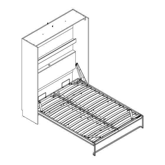
Queen Wall Bed
Date of Purchase ___ / ___ / ___
Lot Number:
WARNING:
* WARNING FOR YOUNG CHILDREN -
This product contains small components,
please ensure that they are kept away
from small children. Children under the
age of 6, small infants and babies must
not sleep on this bed for safety reasons.
To prevent injury and damage to this unit,
PROHIBIT jumping on it.
* This product is designed for home use
and not intended for commercial use.
Do Not Return This Product!
Contact our customer service team for help first.
Call: 1-800-489-3351 (toll free)
Visit: www.ameriwoodhome.com
THIS INSTRUCTION BOOKLET CONTAINS IMPORTANT SAFETY INFORMATION. PLEASE READ AND KEEP FOR FUTURE REFERENCE.
Professional installation is
required for this unit.
WARNING
- Unit can tip over causing severe injury or death.
- Anchor unit to stud in wall
- Do Not allow children to climb on unit
Professional
Easy
Assembly Difficulty Meter
Follow Ameriwood Home
You
Tube
B344335306COM0
Advertisement
Table of Contents

Related Manuals for Novogratz 4335306COM


Summary of Contents for Novogratz 4335306COM
- Page 1 4335306COM Queen Wall Bed B344335306COM0 Date of Purchase ___ / ___ / ___ Lot Number: WARNING: * WARNING FOR YOUNG CHILDREN - This product contains small components, please ensure that they are kept away from small children. Children under the age of 6, small infants and babies must not sleep on this bed for safety reasons.
-
Page 2: Helpful Hints
Contact Us! Do NOT return this product! Contact our friendly customer service team first for help. Assembly Tips Call us! 1-800-489-3351 Monday-Friday 9am - 5pm CST Tube Visit ameriwoodhome.com to view the limited warranty valid in the U.S. and Canada. Helpful Hints PEOPLE NEEDED FOR ASSEMBLY: 2 - Open your item in the area you plan to keep it to avoid excessive heavy lifting. -
Page 3: Before You Start
Before You Start Read through each step carefully and follow the proper order Separate and count all your parts and hardware Parts are labeled on the surface or edge of the part Give yourself enough room for the assembly process Have the following tools: #2 Phillips Head Screwdriver, Hammer, Level, Stud Finder, Pencil, Step Ladder, Rubber Mallet and a Drill with 1/8"... -
Page 4: Board Identification
Board Identification Not actual size ameriwoodhome.com... - Page 5 Board Identification Parts List PART ITEM QTY DESCRIPTION NUMBER 34335306010 LEFT PANEL 34335306020 RIGHT PANEL 34335306030 34335306040 BOTTOM 34335306050 UPPER BACK PANEL 34335306060 CENTER BACK PANEL 34335306070 UPPER SHELF 34335306080 HEADBOARD PANEL 34335306090 BOTTOM STRINGER 34335306100 LOWER SHELF 34335306110 SHELF RAIL 34335306120 LEFT SIDE RAIL 34335306130...
-
Page 6: Part List
Note that your unit may contain extra hardware Part List Actual Size (x26) (x8) (x26) (x10) #A22610 #A13950 #A22620 #A15520 cam bolt #8x3-1/2" pan head cam lock #14 x 1/2" pan (x16) (x4) (x6) (x4) (x28) #A12400 #A43020 #A17400 #A20330 #A21660 #8x5/8"... - Page 7 Note that your unit may contain extra hardware Part List Actual Size (x2) (x13) #A81090 #A53470 wire saddle bracket Not Actual Size shown on pages 31 & 32 (x2) (x1) (x6) A50592 A99570 A54270 handle dual LED light kit connecting plate ATTENTION / ATENCION / ATTENTION (x1) (x1)
- Page 8 Bed Frame Identification Not Actual Size Note: Not all parts will be identified. Mattress Holder (2) Right Assembly Left Assembly 9632096-19c 9632096-19d 9632096-19a 9632096-19b Right Pivot Arm Wood Slat (30) Plastic Cap (60) Left Pivot Arm Gas Piston (4) U-Bracket (4) 9632096-19f 9632096-19e 9632096-19g...
- Page 9 Before you start! VERY IMPORTANT INFORMATION! Caution: Failure to use 2 professionals for this assembly could result in unit damage or personal injury. ameriwoodhome.com...
- Page 10 STEP 1 (x4) (x6) (x1) (x5) Proper orientation of Cam Lock Proper orientation of Cam Lock FLIP finished edge Press in face connector (13) into the holes in the Upper Back Panel (E) then engage the other end of the face connectors (13) into the holes in the Top Rear Rail (N).
- Page 11 STEP 2 (x4) (x8) Proper orientation of Cam Lock Proper orientation of Cam Lock ameriwoodhome.com...
- Page 12 STEP 3 (x6) (x8) (x3) Proper orientation of Connector Proper orientation of Cam Lock Proper orientation of Cam Lock Proper orientation of Cam Lock ameriwoodhome.com...
- Page 13 STEP 4 (x2) (x4) Proper orientation of Cam Lock Proper orientation of Cam Lock ameriwoodhome.com...
- Page 14 STEP 5 (x4) (x3) Proper orientation of Connector ameriwoodhome.com...
- Page 15 STEP 6 (x4) (x3) ameriwoodhome.com...
- Page 16 STEP 7 (x4) (x3) ameriwoodhome.com...
- Page 17 STEP 8 (x1) ameriwoodhome.com...
- Page 18 STEP 9 (x13) (x3) Press in face connector (13) into the holes in the Left Panel (A). Then engage the other end of the face connectors (13) into the holes in the Left Side Rail (L). Press the two parts together to lock together. Please note: the parts will be loose in the holes until you press both parts together.
- Page 19 STEP 10 (x8) The Left Pivot Arm (19e) is located in the 9632096COM Wall Bed Mechanism box ameriwoodhome.com...
- Page 20 STEP 11 (x13) (x3) Press in face connector (13) into the holes in the Right Panel (B). Then engage the other end of the face connectors (13) into the holes in the Right Side Rail (M). Press the two parts together to lock together. Please note: the parts will be loose in the holes until you press both parts together.
- Page 21 STEP 12 (x8) The Right Pivot Arm (19f) is located in the 9632096COM Wall Bed Mechanism box ameriwoodhome.com...
- Page 22 STEP 13 Turn clockwise to lock in place Please note: Shelf Rail (K) is symmetrical. ameriwoodhome.com...
- Page 23 STEP 14 Turn clockwise to lock in place unfinished surface unfinished edge ameriwoodhome.com...
- Page 24 STEP 15 Dowel is closer to the edge here Please note: Top Rear Rail (N) is assembled on finished surface of Upper Back Panel (E). First, assemble Upper Back Panel (E) to Left Panel (A). Then, assemble one of the Center Back Panels (F) to Left Panel (A).
- Page 25 STEP 16 Press dowels into place. Gently use rubber mallet if needed. ameriwoodhome.com...
- Page 26 STEP 17 Dowel is closer to the edge here unfinished surface ameriwoodhome.com...
- Page 27 STEP 18 unfinished surface ameriwoodhome.com...
- Page 28 STEP 19 unfinished edge finished edge ameriwoodhome.com...
- Page 29 STEP 20 Start at one end and work your way to the other end to line parts up before locking cams ameriwoodhome.com...
- Page 30 STEP 21 (x4) (x4) With the help of another person, gently lay the unit onto it's front so the glides will be facing the wall. Tap in bushings (7) with a hammer. Screw in adjustable glides (6) all the way. ameriwoodhome.com...
- Page 31 STEP 22 Electrical hardware Cord length information: 1. The power supply cord is 72 from transformer to the plug's tip 2. The loop wire for the sensor disk, from the transformer is 48 to the center of the loop 3. The light wire that ends in a clip (that will eventually be connected to the light module), that wire, from the transformer is 100 to the clip 4.
- Page 32 STEP 22 continued... LED Light Kit Assembly Open the package for the LED Light Kit. Everything will be assembled together. First, unclip the LED Light from the Light Plug as shown... unclip light plug LED light Second, you must disassemble the LED Light. Unscrew the cover off the base and then remove the lens piece.
- Page 33 STEP 23 (x2) (x1) (x1) Place transformer (24a) on the Headboard Panel (H) in the location shown. Use screw (14) to attach transformer (24a). Thread the power supply plug (24b) in front of the Bottom Stringer (I) if needed for power source. ameriwoodhome.com...
- Page 34 STEP 24 (x1) With the help of another person, carefully stand the unit upright. During these steps, allow another person to securely hold the unit from tipping over. Place touch sensor disk (25) in location shown in Lower Shelf (J). ameriwoodhome.com...
- Page 35 STEP 25 (x1) (x1) With the help of another person holding the unit steady upright, take the Loop Sensor (24c) that is connected to the Transformer (24a) and place underneath the Lower Shelf (J) at the hole location of the Touch Sensor Disk (25). Thread screw (15) through the Loop Sensor and screw into Touch Sensor Disk (25).
- Page 36 The next steps are to assemble your unit to the wall Assembled unit MUST be square on the height, width, and depth to function properly Assembled unit MUST be placed flat against the wall Assembled unit MUST be screwed into 3 DIFFERENT wall studs at the top and bottom for safety Screws provided are for drywall and wood studs.
- Page 37 STEP 26 With the help of another person, place your unit FLUSH against the wall Be sure the light plug wires (24d) are secure in the wire saddle (20) located on Upper Back Panel (E). wire saddle (20) Do NOT cut into bed There are notches provided at the back of your unit.
- Page 38 STEP 27 Assembled unit MUST be flush on the height, width, and depth to function properly A step ladder will be required. Do not lean against the top of the unit, it may cause sagging If required, unscrew the Glides counter-clockwise as necessary in all four corners until your unit is level in all directions...
- Page 39 STEP 28 You need to locate at least 3 DIFFERENT studs, in the horizontal direction, but 4 is better. Stud Stud Stud Stud Locate the studs in the wall, using a stud finder.Using a pencil, mark the stud locations on the upper surface of the Upper Back Panel (E) just under the Top Rear Rail (N).Using a level, carry the stud locations down to...
- Page 40 STEP 29 (x8) First, make sure that your unit is still level in all directions. Drill 1/8" (3mm) pilot holes through the Upper Back Panel (E) and Bottom Stringer (I) at the stud locator marks. Fasten the unit to the studs in the wall with the screws (3). A step ladder will be required.
- Page 41 The next steps are to assemble the metal bed frame and mechanism These parts are located in the #9632096COM Wall Bed Mechanism Carton ameriwoodhome.com...
- Page 42 STEP 30 (x3) (x4) (x1) press in each hole May need a rubber mallet ameriwoodhome.com...
- Page 43 STEP 31 (x8) (x1) (x8) (x4) ameriwoodhome.com...
- Page 44 STEP 32 (x1) (x4) (x2) ameriwoodhome.com...
- Page 45 STEP 33 (x4) (x4) (x4) long end short end The "long" end of each piston is to be fastened to the frame long end long end The ends of both pistons need to be inserted into the groove of the bed frame when assembled. ameriwoodhome.com...
- Page 46 STEP 34 (x1) (x2) (x2) The cabinet is not shown to allow a clear view of the bed frame assembly With a person on each side, lift the bed Pistons have been removed mechanism, line up the holes of the Bed from image to better view step Assembly with the large bushing hole of the Left and Right Pivot arm (19e &...
- Page 47 STEP 35 (x4) (x1) With a person on each side, carefully lift the bed frame in the closed position. While one person pushes the bed frame into the cabinet, passed the 90 degrees, the other person is to engage the "front" Gas Piston (19h) on each side of the unit, to the front pin of the Left and Right Pivot Arm (19e &...
- Page 48 STEP 35 continued... Image is showing the bed frame pushed into the cabinet, passed 90 degrees. Please note: it is normal to see the bed frame in this state prior to the gas pistons being installed. ameriwoodhome.com...
- Page 49 STEP 36 ATTENTION / ATENCION / ATTENTION (x2) (x2) (x1) (x1) The cabinet is not shown to allow a clear view of the bed frame assembly Pull the bed frame down, then attach Leg (19c) as shown Apply Warning Label here The bed frame is equipped with a locking mechanism to lock the Leg (19c) in place.
- Page 50 STEP 37 (x4) A step ladder will be required for this step. With the help from another person, carefully place the Top (C) onto the Left Side Rail (L), Right Side Rail (M) and Top Rear Rail (N). Use screw (10) as shown.
- Page 51 STEP 38 (x2) (x2) A step ladder will be required for this step. With the help of another person, assemble the disassembled LED lights (24d) to the Top (C) with screw (11). Thread the LED lights (24d) wires through the holes provided in Top (C) to allow the wires to be placed on top of the Top (C).
- Page 52 STEP 39 (x2) clip back together LED light light plug With the help of another person, feed the LED light wires through the wire saddle (20) in the Top (C) and through the one on the top edge of the Upper Back Panel (E) if needed. Clip the Light Plugs (24d) (that is fixated into the transformer (24a)) back into the LED light wires.
- Page 53 STEP 40 A step ladder will be required for this step. With the help of another person, assemble the LED lights back together. First placing the lens into the base and then screwing the cover back to the base as shown below. base lens cover...
- Page 54 STEP 41 (x3) (x6) unfinished edge ameriwoodhome.com...
- Page 55 STEP 42 (x4) (x2) unfinished edge ameriwoodhome.com...
- Page 56 STEP 43 (x3) (x10) (x2) ameriwoodhome.com...
- Page 57 STEP 44 (x2) (x4) (x6) With help from another person, hold the Upper Vertical (O) upright & steady and place the Center Panel (S) behind the brackets, pressing the panel flush with the metal plate (23). Use screw (12) to assemble the two parts together.
- Page 58 STEP 45 (x2) (x4) ameriwoodhome.com...
- Page 59 STEP 46 Support Rail IMPORTANT: First, unlock and flip the leg into the cabinet. Then, lower the bed frame down a bit to allow clearance to hook door panels (O,P,Q,R & S) With the help of another person, position the Lower Vertical (P) on the right side of the bed frame.
- Page 60 STEP 47 Support Rail With the help of another person, lower the bed frame to the open position. One person will need to hold the bed frame in the open position while the other person places the Lower Horizontal (R). Position the Lower Horizontal (R) to the left of the Lower Vertical (P).
- Page 61 STEP 48 With one person continuing to hold the bed frame open, another person will assemble the door brackets (21). (x2) (x2) (x2) Do not fully tighten these screw Do not fully tighten these screw ameriwoodhome.com...
- Page 62 STEP 49 Support Rail With the help of another person, close the bed frame. Position the assembled Upper Vertical (O) and Center Panel (S) to the left of the Lower Vertical (P) and on top of Lower Horizontal (R). Lift the assembled Upper Vertical (O) and Center Panel (S), position the Brackets (27) over the...
- Page 63 STEP 50 Support Rail With the help of another person, position the Upper Horizontal (Q) on top of the Lower Vertical (P). Lift the Upper Horizontal (Q), position the Brackets (27) over the upper Support Rail of the Bed Frame, and drop into position.
- Page 64 STEP 51 (x16) (x4) With the help from another person, carefully pull the bed frame open. Place the 4 remaining metal plates (23) as shown. Ensure there are no gaps between the panels. Use screw (12) to fasten metal plates (23). The cabinet is not shown to allow a clear view of the bed frame assembly...
- Page 65 STEP 52 (x3) (x11) (x8) (x11) Tighten all screws in this step Refer next page for These two brackets (19) are bracket locations already in position . and screws used. Align the entire assembly so that the edges are lined up with the bed frame and push up against the leg.
- Page 66 STEP 52 continued... View is looking from the top... showing location of brackets (21). BLACK CIRCLES : The locations to use Screw (18) & Screw (12) to fasten the bracket (21). RED CIRCLES : The locations to use Screw (2) & Screw (12) to fasten the bracket (21). These two brackets (19) are in position already.
- Page 67 STEP 53 (x60) (x30) Press a Plastic Cap (19j) at each end of a Wood Slat (19g). Press both Plastic Caps (19j), attached to the Wood Slat, into the holes of the Metal Bed Frame. Repeat the procedure for all 30 wood slats and 60 plastic caps.
- Page 68 Maximum Loads This unit has been designed to support the maximum loads shown. Exceeding these load limits could cause sagging, instability, product collapse, and/or serious injury. This bed is designed to accommodate a Queen Size Mattress, up to 10" inches thick. * with a maximum weight of 70 lbs (31.8 kgs) * with a minimum weight of 35 lbs (15.9 kgs) After you have finished assembling...
- Page 69 Register your product to receive the following: * New trend details - sneak peek on what's new * Surveys - have a voice within our community * Exclusive deals and discount codes * Quick and easy replacement part service To register your product, visit ameriwoodhome.com Visit your local retailer's website, rate your purchased product and leave us some feedback! ameriwoodhome.com...
- Page 70 Espa ol Cubierta Delantera Cama Queen Wall Fecha de compra N mero de lote ADVERTENCIA: * ADVERTENCIA PARA NI OS PEQUE OS: Este producto tiene piezas peque as, aseg rese de mantenerlas fuera del alcance de los ni os peque os. Los ni os menores de 6 a os, lactantes peque os y beb s no deben dormir en esta cama por cuestiones de seguridad.
- Page 71 Espa ol Consejos de montaje Consejos tiles PERSONAS NECESARIAS PARA EL ENSAMBLAJE: 2 - Abra el art culo en la zona donde piensa colocarlo para evitar levantarlo por su peso. - Identifique, clasifique y cuente las piezas antes de intentar ensamblarlo. - Aseg rese de orientar siempre la punta que est en la parte superior del bloqueo de leva hacia el borde exterior.
- Page 72 Espa ol Lista de piezas N mero de pieza Descripci n Art culo Cantidad Panel izquierdo 34335356010 34335356020 Panel derecho Pieza superior 34335356030 34335356040 Pieza inferior Panel trasero superior 34335356050 34335356060 Panel trasero central Estante superior 34335356070 34335356080 Panel de la cabecera 34335356090 Travesano inferior 34335356100...
- Page 73 Espa ol P gina 8: Identificaci n del marco de cama No es el tama o real Nota: No se identificar n todas las piezas. 19a - Ensamblaje izquierdo 19b - Ensamblaje derecho 19k - Pasador giratorio 19c - Pata 19l - Pasador de horquilla grande 19d - Soporte de colch n 19m - Pasador de horquilla peque o...
- Page 74 Espa ol P gina 13: Paso 4 Orientaci n correcta del bloqueo de leva P gina 14: Paso 5 Orientaci n correcta del conector P gina 18: Paso 9 Introduzca el conector frontal (13) en los orificios del panel izquierdo (A). Luego encaje el otro extremo de los conectores frontales (13) en los orificios del riel lateral izquierdo (L).
- Page 75 Espa ol P gina 24: Paso 15 Primero, ensamble el panel posterior superior (E) al panel izquierdo (A). Luego ensamble uno de los paneles traseros centrales (F) al panel izquierdo (A). El pasador est m s cerca del borde aqu Nota: El riel trasero superior (N) se ensambla en la superficie acabada del panel trasero superior (E).
- Page 76 Espa ol Disco sensor t ctil (empaquetado por separado) El disco sensor t ctil tiene 3 opciones de brillo. - Toque 1: luz nocturna - Toque 2: luz de bajo consumo - Toque 3: luz de lectura brillante - Toque 4: apagado Tenga en cuenta que las herramientas de ensamblaje no est n incluidas en estos paquetes.
- Page 77 Espa ol P gina 36: Los siguientes pasos son ensamblar su unidad a la pared SE REQUIERE INSTALACI N PROFESIONAL La unidad ensamblada DEBE ser cuadrada en la altura, el ancho,y profundidad para funcionar correctamente La unidad ensamblada DEBE colocarse plana contra la pared La unidad ensamblada DEBE atornillarse en 3 DIFERENTES Montantes de pared en la parte superior e inferior para mayor seguridad Los tornillos provistos son para paneles de yeso y montantes de madera.
- Page 78 Espa ol P gina 40: Paso 29 En primer lugar, aseg rese de que la unidad sigue nivelada en todas las direcciones. Taladre orificios gu a de 1/8" (3 mm) a trav s del panel posterior superior (E) y el travesa o inferior (I) en las marcas de localizaci n de las clavijas.
- Page 79 Espa ol P gina 48: Paso 35 continuaci n... Pasados 90 grados La imagen muestra el marco de cama empujado dentro del gabinete, pasados 90 grados. Nota: Es normal ver el marco de cama en este estado antes de instalar los pistones de gas. P gina 49: Paso 36 No se muestra el gabinete para permitir una visi n clara del conjunto del marco de cama.
- Page 80 Espa ol P gina 54: Paso 41 Borde sin acabado P gina 55: Paso 42 Borde sin acabado P gina 57: Paso 44 Con la ayuda de otra persona, sostenga la vertical superior (O) en posici n recta y estable y coloque el panel central (S) detr s de los soportes, presionando el panel al ras de la placa met lica (23).
- Page 81 Espa ol P gina 63: Paso 50 Con la ayuda de otra persona, coloque la horizontal superior (Q) encima de la vertical inferior (P). Levante la horizontal superior (Q), coloque los soportes (27) sobre el riel de soporte superior del marco de cama y col quelos en su posici n.
- Page 82 Espa ol P gina 68: Cargas m ximas Esta unidad est dise ada para soportar las cargas m ximas indicadas. Exceder estos l mites de carga podr a causar pandeo, inestabilidad, colapso del producto o lesiones graves. Esta cama est dise ada para acomodar un colch n Queen, de hasta 25,4 cm (10 pulgadas) de grosor.
- Page 83 Fran ais Page de couverture Lit mural Queen Size Date d achat Num ro de lot AVERTISSEMENT : * AVERTISSEMENT POUR LES JEUNES ENFANTS : Ce produit contient de petits l ments, veuillez vous assurer qu'ils sont tenus l' cart des jeunes enfants. Les enfants de moins de six ans, les nourrissons et les b b s ne doivent pas dormir sur ce lit pour des raisons de s curit .
- Page 84 Fran ais Conseils d assemblage Conseils utiles PERSONNES N CESSAIRES POUR L'ASSEMBLAGE : 2 - Ouvrez votre article l'endroit o vous pr voyez de le conserver afin d' viter de le soulever trop lourdement. - Identifiez, triez et comptez les pi ces avant de proc der l'assemblage. - Veillez toujours orienter la pointe de la partie sup rieure de la serrure came vers le bord ext rieur.
- Page 85 Fran ais Liste des pi ces Num ro de pi ce Description de l'article Quantit Article Panneau gauche 34335356010 34335356020 Panneau droit 34335356030 Dessus 34335356040 Dessous Panneau arriere superieur 34335356050 34335356060 Panneau arriere central Etagere superieur 34335356070 34335356080 Panneau de tete de lit 34335356090 Traverse inferieure Etagere inferieure...
- Page 86 Fran ais Page 8: Identification du cadre de lit Taille non r elle Remarque : toutes les pi ces ne sont pas identifi es. 19a - Cadre gauche 19k - Goupille de pivot 19b - Cadre droit 19l - Grande broche de chape 19c - Jambe 19m - Petite broche de chape 19d - Support de matelas...
- Page 87 Fran ais Page 14 : tape 5 Orientation correcte du connecteur Page 18 : tape 9 Enfoncez le connecteur de face (13) dans les trous du panneau gauche (A). Engagez ensuite l'autre extr mit des connecteurs de face (13) dans les trous du rail lat ral gauche (L). Appuyez sur les deux parties pour les verrouiller.
- Page 88 Fran ais Page 26 : tape 17 Surface non finie La cheville est plus proche du bord ici Page 27 : tape 18 Surface non finie Page 28 : tape 19 Bord non fini bord fini Page 29 : tape 20 Commencez une extr mit et allez jusqu' l'autre extr mit pour aligner les pi ces avant de verrouiller les serrures came.
- Page 89 Fran ais Le disque de d tection tactile a trois options de luminosit . - Touche 1 : lumi re de nuit - Touche 2 : lumi re d' conomie d' nergie - Touche 3 : lumi re de lecture brillante - Touche 4 : teindre Veuillez noter que le mat riel d'assemblage n'est pas inclus dans ces paquets.
- Page 90 Fran ais Une fois la vis (15) compl tement serr e, faites remonter les fils de la prise d' clairage (24d) le long de la face arri re de l'appareil. Faites passer les fils travers le collier de serrage (20) sur le bord sup rieur du panneau arri re sup rieur (E).
- Page 91 Fran ais Page 39 : tape 28 Localisez les montants dans le mur l'aide d'un d tecteur de montants. l'aide d'un crayon, marquez l'emplacement des montants sur la surface sup rieure du panneau arri re sup rieur (E), juste sous la traverse arri re sup rieure (N).
- Page 92 Fran ais Avec une personne de chaque c t , soulevez le m canisme du lit, alignez les trous de l'assemblage du lit avec le grand trou du bras pivotant gauche et droit (19e et 19f) d j install sur votre unit , et ins rez les goupilles pivotantes (19k) comme indiqu .
- Page 93 Fran ais Le m canisme du cadre de lit a t retir pour mieux illustrer cette tape. Trou pour le fil Page 52 : tape 39 Remettez le clip en place Bouchon de la lumi re Lumi re DEL Avec l'aide d'une autre personne, faites passer les fils de la lumi re DEL dans le collier de serrage (20) de la partie sup rieure (C) et dans celui situ sur le bord sup rieur du panneau arri re sup rieur (E) si n cessaire.
- Page 94 Fran ais Avec l'aide d'une autre personne, positionnez la verticale inf rieure (P) sur le c t droit du cadre de lit. Soulevez la colonne verticale inf rieure (P), placez les supports (27) sur les deux rails de support inf rieurs du cadre de lit et mettez-les en place. L'armoire n'est pas montr e pour permettre une vue claire de l'assemblage du cadre de lit.
- Page 95 Fran ais Page 65 : tape 52 Serrez toutes les vis cette tape! Reportez-vous la page suivante pour emplacements des supports et vis utilis es. Ces deux supports (21) sont d j en position. Alignez l'ensemble de mani re ce que les bords soient align s avec le cadre du lit et poussez contre le pied.
- Page 96 Fran ais Page 69 : enregistrez votre produit pour recevoir les informations suivantes : * D tails des nouvelles tendances : un aper u de ce qui est nouveau * Sondages : faites entendre votre voix au sein de notre communaut * Offres exclusives et codes de r duction * Service de remplacement de pi ces rapide et facile Pour enregistrer votre produit, rendez-vous sur ameriwoodhome.com...
Need help?
Do you have a question about the 4335306COM and is the answer not in the manual?
Questions and answers