Table of Contents
Advertisement
Quick Links
Advertisement
Table of Contents

Related Manuals for Sharp R-305DW


Summary of Contents for Sharp R-305DW
- Page 1 This Owner's Manual is provided and hosted by Appliance Factory Parts. Sharp R305DW Owner's Manual Shop genuine replacement parts for Sharp R305DW Find Your Sharp Microwave Parts - Select From 1193 Models -------- Manual continues below --------...
-
Page 2: Table Of Contents
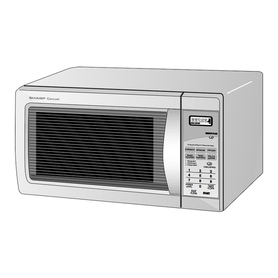
R -305DW SERVICE MANUAL S3006R305DPW/ MICROWAVE OVEN R-305DW MODEL LBS. CUPS. COOK DEFOST MINUTE PLUS TO ADJUST QUANTITY TOUCH PAD AGAIN CASSEROL E BEVERAGE POPCORN BAKED FRESH ROLLS & POTATOES VEGETABLE S MUFFINS 1 GROUND MEAT 2 STEAKS/CHOP S 3 CHICKEN PIECES... -
Page 3: Precautions To Be Observed Before And During Servicing To Avoid Possible Exposure To Excessive Microwave Energy
Before servicing an operative unit, perform a microwave emission check as per the Microwave Measurement Procedure outlined in this service manual. If microwave emissions level is in excess of the specified limit, contact SHARP ELECTRONICS CORPORATION immediately @1-800-237-4277. If the unit operates with the door open, service person should 1) tell the user not to operate the oven and 2) contact SHARP ELECTRONICS CORPORATION and Food and Drug Administration's Center for Devices and Radiological Health immediately. -
Page 4: Warning To Service Personnel
R-305DW WARNING TO SERVICE PERSONNEL Microwave ovens contain circuitry capable of pro- ducing very high voltage and current, contact with following parts may result in a severe, possibly fatal, electrical shock. (Example) High Voltage Capacitor, High Voltage Power Trans- former, Magnetron, High Voltage Rectifier Assem- bly, High Voltage Harness etc.. -
Page 5: Microwave Measurement Procedure
R-305DW MICROWAVE MEASUREMENT PROCEDURE A. Requirements: 1) Microwave leakage limit (Power density limit): The power density of microwave radiation emitted by a microwave oven should not exceed 1mW/cm at any point 5cm or more from the external surface of the oven, measured prior to acquisition... -
Page 6: Foreword And Warning
MICROWAVE OVEN R-305DW GENERAL INFORMATION FOREWORD This Manual has been prepared to provide Sharp Electronics Corp. Service Personnel with Operation and Service Information for the SHARP MICROWAVE OVEN, R-305DW. OPERATION It is recommended that service personnel carefully study the entire text of this manual so that they will be qualified to render satisfactory customer service. -
Page 7: Product Specifications
R-305DW SPECIFICATION ITEM DESCRIPTION Power Requirements 120 Volts / 13 Amperes 60 Hertz Single phase, 3 wire grounded Power Output 1100 watts (IEC TEST PROCEDURE) Operating frequency of 2450MHz Case Dimensions Width 20-1/2" Height 11-7/8" Depth 17-1/8" Cooking Cavity Dimensions Width 14-3/4"... -
Page 8: Oven Diagram
R-305DW contact a qualified electrician and have it replaced with a properly Grounded 3-Pronged Plug grounded three-pronged wall receptacle or have a grounding adapter Receptacle Box properly grounded and polarized. If the extension cord must be used, it should be a 3-wire, 15 amp. or higher rated cord. Do not drape over a countertop or table where it can be pulled on by children or tripped over accidentally. -
Page 9: Operation
R-305DW OPERATION DESCRIPTION OF OPERATING SEQUENCE The following is a description of component functions during relay and is mechanically associated with the door so oven operation. that it will function in the following sequence. (1) When the door opens from the closed position, the... - Page 10 R-305DW SCHEMATIC NOTE: CONDITION OF OVEN 1. DOOR CLOSED NOTE: Indicates components with potential above 250 V. 2. CLOCK APPEARS ON DISPLAY THERMAL MONITOR THERMAL CUT-OUT (OVEN) FUSE 20A CUT-OUT (MG.) N.O. POWER N.O. TRANSFORMER (RY-2) (RY-1) PRIMARY INTERLOCK RELAY CONTROL UNIT COM.
-
Page 11: Description And Function Of Components
R-305DW DESCRIPTION AND FUNCTION OF COMPONENTS DOOR OPEN MECHANISM CAUTION: BEFORE REPLACING A BLOWN MONITOR FUSE TEST THE DOOR SENSING SWITCH, The door is opened by pulling the door. Refer to the Figure PRIMARY INTERLOCK RELAY (RY2), RELAY D-1. (RY1), SECONDARY INTERLOCK SWITCH... -
Page 12: Troubleshooting Guide
R-305DW TROUBLESHOOTING GUIDE Never touch any part in the circuit with your hand or an uninsulated tool while the power supply is connected. When troubleshooting the microwave oven, it is helpful to follow the Sequence of Operation in performing the checks. Many of the possible causes of trouble will require that a specific test be performed. -
Page 13: Test Procedure
R-305DW CK = Check / RE = Replace RE RE A B C D E F F G H RE RE CK I CK CK CK J K L M TEST PROCEDURE PROBLEM CONDITION Home fuse or circuit breaker blows... - Page 14 R-305DW TEST PROCEDURES PROCEDURE COMPONENT TEST LETTER 4. To test for an open filament, isolate the magnetron from the high voltage circuit. A continuity check across the magnetron filament leads should indicate less than 1 ohm. 5. To test for a shorted magnetron, connect the ohmmeter leads between the magnetron filament leads and chassis ground.
- Page 15 R-305DW TEST PROCEDURES PROCEDURE COMPONENT TEST LETTER HIGH VOLTAGE RECTIFIER TEST 1. Disconnect the power supply cord, and then remove outer case. 2. Open the door and block it open. 3. Discharge high voltage capacitor. 4. Isolate the rectifier from the circuit. Using the highest ohm scale of the meter, read the resistance across the terminals and observe, reverse the leads to the rectifier terminals and observe meter reading.
- Page 16 R-305DW TEST PROCEDURES PROCEDURE COMPONENT TEST LETTER CAUTION: IF THE THERMAL CUT-OUT INDICATES AN OPEN CIRCUIT AT ROOM TEMPERATURE, REPLACE THERMAL CUT-OUT. SECONDARY INTERLOCK SWITCH TEST 1. Disconnect the power supply cord, and then remove outer case. 2. Open the door and block it open.
-
Page 17: Component Test
R-305DW TEST PROCEDURES PROCEDURE COMPONENT TEST LETTER 5. Reconnect all leads removed from components during testing. 6. Reinstall the outer case (cabinet). 7. Reconnect the power supply cord after the outer case is installed. 8. Run the oven and check all functions. -
Page 18: Key Unit Test
R-305DW TEST PROCEDURES PROCEDURE COMPONENT TEST LETTER b) When touching a number pad, two figures or more are displayed. c) When touching the pads, sometimes a pad produces no signal. If the Key unit is defective. 1) Disconnect the power supply cord, and then remove outer case. - Page 19 R-305DW TEST PROCEDURES PROCEDURE COMPONENT TEST LETTER 7. Reconnect the power supply cord after the outer case is installed. 8. Run the oven and check all functions. MINUTE ROLLS & PLUS MUFFINS FRESH VEGETABLES POWER TIMER COMPU CASSEROLE POPCORN START...
- Page 20 R-305DW TEST PROCEDURES PROCEDURE COMPONENT TEST LETTER FOIL PATTERN ON THE PRINTED WIRING BOARD TEST To protect the electronic circuits, this model is provided with a fine foil pattern added to the primary on the PWB, this foil pattern acts as a fuse.
-
Page 21: Touch Control Panel
R-305DW TOUCH CONTROL PANEL ASSEMBLY OUTLINE OF TOUCH CONTROL PANEL The touch control section consists of the following units. 3) Power Source Circuit This circuit generates voltages necessary in the control (1) Key Unit unit from the AC line voltage. - Page 22 R-305DW Pin No. Signal Description Back light circuit (Light emitting diodes) driving signal. 12-13 P56-P55 Terminal not used. CNTR0 Signal to sound buzzer (2.0 kHz). 0.1 sec. H : GND A: Key touch sound. L : -5V B: Completion sound.
- Page 23 R-305DW Pin No. Signal Description Key strobe signal. Signal applied to touch-key section. A pulse signal is input to P41, P43, P44 and P45 terminal while one of G8 line keys on key matrix is touched. Key strobe signal. Signal applied to touch-key section. A pulse signal is input to P41, P43, P44 and P45 terminal while one of G7 line keys on key matrix is touched.
-
Page 24: Touch Control Panel Servicing
R-305DW TOUCH CONTROL PANEL SERVICING A. On some models, the power supply cord between the 1. Precautions for Handling Electronic Components touch control panel and the oven itself is so short that the This unit uses CMOS LSI in the integral part of the two can’t be separated. -
Page 25: Component Replacement And Adjustment Procedure
WARNING FOR WIRING To prevent an electric shock, take the following pre- and Oven cavity. cautions. 3) Sharp edge: 1. Before wiring, Bottom plate, Oven cavity, Waveguide flange, 1) Disconnect the power supply cord. Chassis support and other metallic plate. - Page 26 R-305DW CAUTION: 1. DISCONNECT OVEN FROM POWER SUP NOTE: When replacing the outer case, the 2 special PLY BEFORE REMOVING OUTER CASE. Torx screws must be reinstalled in the same 2. DISCHARGE THE HIGH VOLTAGE CA- locations. PACITOR BEFORE TOUCHING ANY OVEN COMPONENTS OR WIRING.
-
Page 27: Oven Lamp And Lamp Socket Removal
R-305DW 9. Now, the magnetron is free. 4. Reconnect the wire leads to the magnetron and thermal Reinstallation cut-out (MG). Refer to "PICTORIAL DIAGRAM" on page 1. Re-install the magnetron to waveguide flange with the four (4) screws. 5. Re-install outer case and check that the oven is operating 2. -
Page 28: Turntable Motor Removal
4. Where the corners have been snipped off bend corner 7. Now the turntable motor is free. areas flat. No sharp edges must be evident after removal 8. After replacement use the one (1) screw to fit the of the turntable motor cover. -
Page 29: Door Sensing Switch/Secondary Interlock Switch And Monitor Switch Removal
R-305DW DOOR SENSING SWITCH/SECONDARY INTERLOCK SWITCH AND MONITOR SWITCH REMOVAL Reinstallation 1. Disconnect the power supply cord and remove outer case. 2. Open the door and block it open. 1. Re-install each switch in its place. The secondary 3. Discharge high voltage capacitor. -
Page 30: Sealer Film
R-305DW 11.Now, door panel with sealer film is free. 12.Tear sealer film from door panel. 13.Now, door panel is free. Upper Oven 14.Slide latch head upward and remove it from door frame Upper Hinge Oven Hinge with releasing latch spring from door frame and latch head. -
Page 31: Pictorial Diagram
R-305DW... -
Page 32: Power Unit Circuit
R-305DW CN-C CN-A 9PIN LEAD WIRE HARNESS S1NB10 – OVEN LAMP TURNTABLE BUZZER MOTOR FAN MOTOR OVEN LAMP TURNTABLE MOTOR FAN MOTOR MICRO MICRO SH-A DOOR DOOR SENSING SH-B SWITCH SENSING SWITCH... -
Page 33: Cpu Unit Circuit
R-305DW... -
Page 34: Printed Wiring Board
R-305DW SH - B CN - C (D2) (D3) CN - A Figure S-4. Printed Wiring Board of Power Unit... -
Page 35: Parts List
R-30 5DW PARTS LIST ∆ Note: The parts marked “ ” may cause undue microwave exposure. The parts marked “*” are used in voltage more than 250V. REF. NO. PART NO. DESCRIPTION Q'TY CODE ELECTRIC PARTS 1- 1 QSW-MA147WRZZ 2nd interlock switch / door sensing switch 1- 2 QFSHDA009WRE0 Fuse holder... -
Page 36: Screws,Nuts And Washers
To have your order filled promptly and correctly, please furnish the following information. 1. MODEL NUMBER 2. REF. NO. 3. PART NO. 4. DESCRIPTION Order Parts from the authorized SHARP parts Distributor for your area. Defective parts requiring return should be returned as indicated in the Service Policy. -
Page 37: Oven And Cabinet Parts
R-30 5DW OVEN AND CABINET PARTS 4-18 1-10 1-11 4-17 4-20 4-13 4-11 4-19 4-10 4-20 4-18 4-12 4-16 4-15 1-13 4-14 1-12 1-14 4-21... -
Page 38: Door Parts
R -305DW CONTROL PANEL PARTS DOOR PARTS 3-3-1 MISCELLANEOUS (CAPACITOR) Actual wire harness may be different from illustration. -
Page 39: Packing And Accessories
R-30 5DW TOP PAD ASSEMBLY FPADBA416WRKZ PACKING AND ACCESSORIES DOOR PROTECTION SHEET SPADPA204WRE0 PLASTIC BAG SSAKHA034WRE0 6- 8 INSTRUCTION BOOK & PRINTING MATTER 6- 2 TURNTABLE TRAY BOTTOM PAD ASSEMBLY FPADBA417WRKZ 6- 1 TURNTABLE SUPPORT TRAY PACK INTO THE SPADFA451WRE0 OVEN CAVITY Not replaceable items. - Page 40 R -305DW...
-
Page 41: All Rights Reserved
No part of this publication may be repro- duced, stored in retrieval systems, or trans- mitted in any form or by any means, elec- tronic, mechanical, photocopying, record- ing, or otherwise, without prior written per- mission of the publisher. 2000 SHARP CORP. (3S2.530E) Printed in U.S.A...
Need help?
Do you have a question about the R-305DW and is the answer not in the manual?
Questions and answers