Table of Contents
Advertisement
Available languages
Available languages
Quick Links
MASTERFORGE and logo design are
trademarks or registered trademarks of LF, LLC.
All rights reserved.
Before the first use of this heater, please read this OWNER'S MANUAL very carefully. This OWNER'S
MANUAL has been designed to instruct you as to the proper manner in which to assemble the heater,
maintain the heater, store the heater, and most importantly, how to operate the heater in a safe and
efficient manner, please keep this manual for future reference.
Serial Number
Purchase Date
Thank you for purchasing this MASTER FORGE product.
Questions, problems, missing parts? Before returning contact us on: 1-877-447-4768, 8:30
a.m. – 4:30 p.m., CST, Monday – Friday or email us at customerservice@ghpgroupinc.com.
SG24120
CONVECTION
WICK HEATER
ATTACH YOUR RECEIPT HERE
1
ITEM #5697452
MODEL #WK95C8M
Español P. 23
WK95C8M - 2024-03-25
Advertisement
Chapters
Table of Contents

Related Manuals for Master Forge WK95C8M

Summary of Contents for Master Forge WK95C8M
- Page 1 Serial Number Purchase Date Thank you for purchasing this MASTER FORGE product. Questions, problems, missing parts? Before returning contact us on: 1-877-447-4768, 8:30 a.m. – 4:30 p.m., CST, Monday – Friday or email us at customerservice@ghpgroupinc.com.
-
Page 2: Cautions / Safety Guide
WARNING This product and the fuel used to operate this product (kerosene or other approved fuels), and the products of combustion of such fuel, can expose you to chemicals including benzene, which is known to the State of California to cause cancer and reproductive harm. For more information go to www.p65Warnings.ca.gov CAUTIONS - SAFETY GUIDE -... -
Page 3: Table Of Contents
TABLE OF CONTENTS Cautions / Safety Guide............. .2 Package Contents . -
Page 4: Hardware Contents
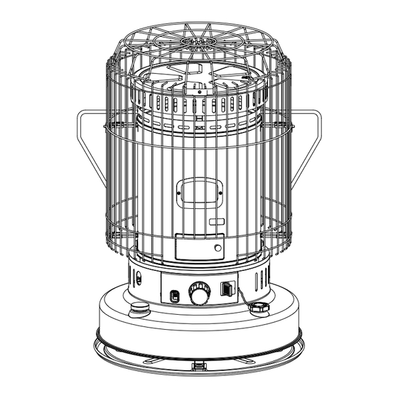
HARDWARE CONTENTS Top Plate Carrying handle Top guard Front guard Rear guard Batteries Siphon pump Screws Qty. 1 Qty. 1 Qty. 1 Qty. 1 Qty. 1 Qty. 2 Qty. 1 Qty. 2 Tools required for assembly (not included): PHILLIPS SCREWDRIVER ASSEMBLY INSTRUCTIONS CAUTION: “RISK OF BURNS”... - Page 5 ASSEMBLY INSTRUCTIONS 3. Align the arrow marking on the top plate (AA) with the carrying handle hole on the cabinet and place arrow the top plate on the heater (A). marking Hardware Used Top Plate carrying handle hole 4. Hang the upper portion of the front guard (DD) (notched to allow for the igniter door) on the Upper Grill brackets with the downward hooked grill rods.
- Page 6 Fig.6 ASSEMBLY INSTRUCTIONS 6. Align the 2 brackets on the top guard (CC) with Fig.6 the 2 mounting brackets on the front (DD) and rear (EE) guards. Secure each bracket with a screw (HH). Make sure that the brackets on the top guard (CC) are positioned outside the mounting brackets on the front (DD) and rear (EE) guards.
-
Page 7: Fueling Your Heater
FUELING YOUR HEATER KEROSENE ONLY (1-K ONLY) It is EXTREMELY IMPORTANT to the operation of this heater that you use the proper grade of kerosene. The proper grade of kerosene is identified as 1-K Kerosene. DO NOT OPERATE THIS HEATER WITH ANY FUEL OTHER THAN 1-K KEROSENE! 1-K Kerosene has been refined to virtually eliminate contaminants such as sulfur, which can cause a rotten egg odor during operation of the heater. -
Page 8: Automatic Ignition System
FUELING YOUR HEATER After fueling the fuel tank of the heater by using siphon pump, make sure that you loosen (counter clockwise) the cap on the siphon pump to drain LOOSEN thoroughly the remaining kerosene in the siphon pump. For the reuse of siphon pump, make sure that you tighten (clockwise) the cap on the siphon pump to transfer the kerosene into the fuel tank properly. - Page 9 IGNITION VIA MATCH If you encounter a problem with the ignition mechanism, or if you have dead batteries, it is possible to light the heater with a match. Match (Fig. 14) The procedure is as follows: • Turn the wick adjuster knob clockwise until the wick has been raised to its maximum height.
-
Page 10: Checking The Ignition System
CHECKING THE IGNITION SYSTEM If the automatic ignition system fails to operate properly, If the automatic ignition system fails to operate properly, perform the following checks: ic ignition system fails to operate properly, • BATTERIES - 2 “C” cell batteries are located at the rear of the heater. perform the following checks: Replace with new batteries. -
Page 11: Wick Maintenance/Dry Burn
ADJUSTING THE WICK NOTE : During start-up, small adjustments to the flame can be performed NOTE: During start-up, small adjustments to the flame can be performed by using the burner knob on the front of the burner and MOVING THE by using the burner knob on the front of the burner and MOVING THE BURNER FROM SIDE TO SIDE until the flame at the top of burner is as BURNER FROM SIDE TO SIDE until the flame at the top of burner is as... -
Page 12: Wick Assembly
WICK ASSEMBLY WICK ASSEMBLY- Check at least once a month!! The burner assembly sits on top of the wick guide. Over time, tar deposits can accumulate on the wick guide, and this can prevent the burner assembly from seating properly. This can result in poor combustion, smoke, odor, etc.. To prevent this from happening, tar deposits on the wick guide can be removed as follows: •... - Page 13 WICK REPLACEMENT 4. Gently pull the wick adjustment knob off the heater. 5. Remove the cabinet base by lifting it from the back and tilting it forward to clear the wick adjuster assembly. 6. Trip the pendulum on the automatic safety shutoff system to lower the wick.
- Page 14 10. Remove the wick by folding it to the inside. Then remove the wick sleeve from the bottom of the assembly. 11. Install the new wick and insert the 3 pins on a new wick into Hole the 3 holes on the wick sleeve in the upward direction. (See the arrow marked “▲...
- Page 15 WICK REPLACEMENT 15. Turn the wick assembly upside down to replace the wick cover. 15 & 16 16. Align the tabs on the wick cover with the four screw holes on the bottom of the assembly, as shown, and snap it into place. Be certain of firm contact at all points.
-
Page 16: Extinguishing The Heater
EXTINGUISHING THE HEATER To extinguish the heater, push down on the manual shut-off knob (Fig.18) with one hand while holding the wick adjuster knob in the other hand. You will feel the pressure of spring action attempting to turn the wick adjuster knob in a counterclockwise direction in your hand. -
Page 17: Long Term Storage Of Your Heater
AUTOMATIC SAFETY SHUT-OFF DEVICE TESTING THE SAFETY SHUT-OFF DEVICE: At least once a week during the heating season, it is important to test the safety shut-off device to be sure that it is operating properly. WITH THE HEATER TURNED OFF, raise the wick using the wick adjuster knob to the fully raised position. Grabbing the protective grill, give the heater a firm shake. -
Page 18: Trouble Shooting Guide
TROUBLESHOOTING PROBLEM POSSIBLE CAUSE CORRECTIVE ACTION Heater Will Not Light. 1. Fuel tank is empty. 1. Fill tank with water-clear 1-K kerosene or red dyed 1-K kerosene. 2. Water present in kerosene. 2. Drain tank. Remove wick assembly & replace wick. Reinstall wick assembly. Fill tank with water-clear1-K kerosene or red dyed 1-K kerosene. -
Page 19: Replacement Parts List
WS-CV21 FUEL GAUGE GASKET WS-CV22 TANK ASS' Y (BLACK) 2111-0088-02 IGNITER ASS' Y 2117-0023-00 WICK SLEEVE PS-CV35 Model No. WK95C8M Type of Heater Convection Heat Output Max. 23,800 BTU/hr Fuel Tank Integral Tank Capacity 1.9 U.S. gallons Continuous Combustion Time Approx. -
Page 20: Specifications
SPECIFICATIONS Model No. WK95C8M Type of Heater Convection Heat Output Max. 23,800 BTU/hr Fuel Tank Integral Tank Capacity 1.9 U.S. gallons Continuous Combustion Time Approx. 8 - 12 hr Max. Fuel Consumption 0.180 U.S. gallons/hr. Ignition Method Battery-C Cell x2, Igniter Type "B"... -
Page 22: Warranty
WARRANTY REGISTRATION IMPORTANT: We urge you to fill out your warranty registration card within fourteen (14) days of date of purchase. You can also register your warranty on the internet at www.ghpgroupinc.com. Complete the entire serial number. Retain this portion of the card for your records. - Page 23 Número de serie Fecha de compra Gracias por comprar este producto MASTER FORGE. ¿Preguntas, problemas, piezas faltantes? Antes de volver a la tienda, póngase en contacto al: 1-877-447-4768, de lunes a viernes de 8:30 a.m. a 4:30 p.m., hora central estándar, o envíenos un correo electrónico a customerservice@ghpgroupinc.com.
-
Page 24: Guía De Seguridad/Precauciones
ADVERTENCIA Este producto y el combustible utilizado para operar este producto (queroseno u otros combustibles aprobados), y los productos de la combustión de dicho combustible, pueden exponerlo a productos químicos, incluido el benceno, que el estado de California reconoce como causante de cáncer y daños al aparato reproductivo. -
Page 25: Contenido Del Paquete
ÍNDICE Guía de seguridad/precauciones............24 Contenido del paquete . -
Page 26: Aditamentos
ADITAMENTOS Tornillos Placa Manija de Protección Protección Protección Baterías Bomba del superior transporte superior frontal posterior sifón Cant. 1 Cant. 1 Cant. 1 Cant. 1 Cant. 1 Cant. 2 Cant. 1 Cant.. 2 Herramientas necesarias para el ensamble (no se incluyen): DESTORNILLADOR PHILLIPS INSTRUCCIONES DE Ensamble PRECAUCIÓN: “PREVENCIÓN DE QUEMADURAS”... - Page 27 INSTRUCCIONES DE Ensamble 3. Alinee la marca de flecha en la placa superior (AA) con el orificio de la manija de transporte en el marca de flecha gabinete y coloque la placa superior en el calentador (A). Aditamentos utilizados Placa superior orificio de la manijade...
- Page 28 Fig.6 INSTRUCCIONES DE Ensamble 6. Alinee los 2 soportes de protección superior (CC) Fig.6 con los 2 soportes de montaje de las protecciones delantera (DD) y posterior (EE). Asegure cada soporte de metal con un tornillo (AA). Asegúrese de que los soportes de la protección superior (CC) estén ubicados fuera de los soportes de montaje en Fig.6 las protecciones delantera (DD) y posterior (EE).
-
Page 29: Abastecimiento De Combustible Para Su Calentador
CÓMO PONERLE COMBUSTIBLE A SU CALENTADOR SOLO QUEROSENO (1-K ÚNICAMENTE) Es EXTREMADAMENTE IMPORTANTE para el funcionamiento de este calentador que utilice el grado adecuado de queroseno. El grado adecuado de queroseno se identifica como queroseno 1-K. ¡NO USE ESTE CALENTADOR CON NINGÚN COMBUSTIBLE QUE NO SEA QUEROSENO 1-K! El queroseno 1-K se refina para eliminar prácticamente contaminantes como el azufre, que puede causar olor a huevo podrido durante el funcionamiento del calentador. -
Page 30: Sistema De Encendido Automático
CÓMO PONERLE COMBUSTIBLE A SU CALENTADOR Después de cargar combustible en el tanque de combustible del calentador con la bomba del sifón, asegúrese de aflojar (en dirección LOOSEN AFLOJAR contraria a las manecillas del reloj) la tapa de la bomba del sifón para drenar completamente el queroseno restante. - Page 31 ENCENDIDO CON FÓSFOROS Si tiene un problema con el mecanismo de encendido o si tiene las Fósforo baterías agotadas, es posible encender el calentador Match con fósforos. (Fig. 14) El procedimiento es el siguiente: • Gire la perilla de ajuste de la mecha en en dirección de las manecillas del reloj hasta que la mecha se haya elevado a su altura máxima.
-
Page 32: Verificación Del Sistema De Encendido
VERIFICACIÓN DEL SISTEMA DE ENCENDIDO Si el sistema de encendido automático no funciona correctamente, realice las siguientes verificaciones: If the automatic ignition system fails to operate properly, ic ignition system fails to operate properly, • BATERÍAS: hay 2 baterías de celda “C” ubicadas en la parte posterior perform the following checks: del calentador. -
Page 33: Ajuste De La Mecha
AJUSTE DE LA MECHA NOTA: durante el encendido, se pueden realizar pequeños ajustes a NOTE : During start-up, small adjustments to the flame can be performed la llama con la perilla del quemador en la parte frontal del quemador by using the burner knob on the front of the burner and MOVING THE y MOVER EL QUEMADOR DE LADO A LADO hasta que la llama BURNER FROM SIDE TO SIDE until the flame at the top of burner is as en la parte superior del quemador se apague lo más uniforme... -
Page 34: Ensamble De La Mecha
Ensamble DE LA MECHA Ensamble DE LA MECHA: ¡revísela al menos una vez al mes! El ensamble del quemador se encuentra encima de la guía de la mecha. Con el tiempo, se pueden acumular depósitos de alquitrán en la guía de la mecha y esto puede impedir que el ensamble del quemador se asiente correctamente. - Page 35 REEMPLAZO DE LA MECHA 4. Retire con cuidado la perilla de ajuste de la mecha del calentador. 5. Retire la base del gabinete levantándola desde la parte posterior e inclinándola hacia adelante para liberar el ensamble del ajustador de la mecha. 6.
- Page 36 REEMPLAZO DE LA MECHA 10. Retire la mecha doblándola hacia el interior. Luego retire la funda de mecha de la parte inferior del ensamble. 11. Instale la nueva mecha e inserte los 3 pasadores de una Hole Orificio mecha nueva en los 3 orificios del manguito de la mecha hacia Pasador arriba.
- Page 37 REEMPLAZO DE LA MECHA 15. Voltee el ensamble de la mecha para reemplazar la cubierta de la mecha. 15 & 16 16. Alinee las pestañas de la cubierta de la mecha con los cuatro orificios para tornillos en la parte inferior del ensamble, como se muestra, y colóquelas en su lugar.
-
Page 38: Apagado Del Calentador
APAGADO DEL CALENTADOR Para apagar el calentador, presione hacia abajo la perilla de apagado manual (Fig. 18) con una mano mientras sostiene la perilla de ajuste de la mecha con la otra. Sentirá la presión de la acción del resorte al intentar girar la perilla de ajuste de la mecha en dirección contraria a las manecillas del reloj en su mano. -
Page 39: Almacenamiento A Largo Plazo De Su Calentador
DISPOSITIVO DE APAGADO AUTOMÁTICO DE SEGURIDAD PRUEBA DEL DISPOSITIVO DE APAGADO DE SEGURIDAD: al menos una vez a la semana durante la temporada de calefacción, es importante probar el dispositivo de apagado de seguridad para asegurarse de que esté funcionando correctamente. CON EL CALENTADOR APAGADO, levante la mecha con la perilla de ajuste de la mecha hasta la posición completamente elevada. -
Page 40: Guía Para La Solución De Problemas
SOLUCIÓN DE PROBLEMAS PROBLEMA CAUSA POSIBLE ACCIÓN CORRECTIVA El calentador no se 1. El tanque de combustible está vacío. 1. Llene el tanque con queroseno 1-K transparente 2. Hay agua en el queroseno. como el agua o queroseno 1-K teñido de rojo. enciende. -
Page 41: Lista De Piezas De Repuesto
ENSAMBLE DE LA CAJA DE BATERÍA 2118-0031-02 (NEGRO) REJILLA FRONTAL PS-CV061 GABINETE (NEGRO) 2118-0054-02 VENTANA DE MICA WS-CV09 Model No. WK95C8M PUERTA (NEGRA) WS-CV34B Type of Heater Convection Heat Output Max. 23,800 BTU/hr INDICADOR DE COMBUSTIBLE WS-CV21 Fuel Tank Integral... -
Page 42: Especificaciones
ESPECIFICACIONES Modelo No. WK95C8M Tipo de calentador Convección Salida de calor Máx. 23.800 BTU/h Tanque de combustible Integral Capacidad del tanque 7.19 litros (1.9 galones estadounidenses) Tiempo de combustión continua Entre 8 y 12 horas, aprox. Consumo de combustible máximo 0.68 litros (0.180 galones estadounidenses/h) -
Page 43: Garantía
Garantía GARANTÍA LIMITADA: Esta garantía limitada se extiende al comprador minorista original de este calentador de aire forzado/convección/radiante y garantiza contra cualquier defecto en materiales y mano de obra por un período de un (1) año a partir de la fecha de venta minorista. GHP Group, Inc., a su elección, proporcionará piezas de repuesto o reemplazará... -
Page 44: Registro De La Garantía
REGISTRO DE LA GARANTÍA IMPORTANTE: lo instamos a llenar su tarjeta de registro de la garantía en el plazo de catorce (14) días después de la fecha de compra. También puede registrar su garantía en internet en www.ghpgroupinc.com. Complete el número de serie. Conserve esta porción de la tarjeta para sus registros.
Need help?
Do you have a question about the WK95C8M and is the answer not in the manual?
Questions and answers
I **** stumped by the very first diagram. How do I get the top cover to hook onto the stove
To attach the top cover (top plate) to the Master Forge WK95C8M stove:
1. Align the arrow marking on the top plate (AA) with the carrying handle hole on the heater cabinet.
2. Place the top plate on the heater so the arrow is aligned properly.
No tools are mentioned for this step, and alignment is key for proper placement.
This answer is automatically generated