Table of Contents
Advertisement
Quick Links
Advertisement
Table of Contents

Summary of Contents for Global Laser MINI Q
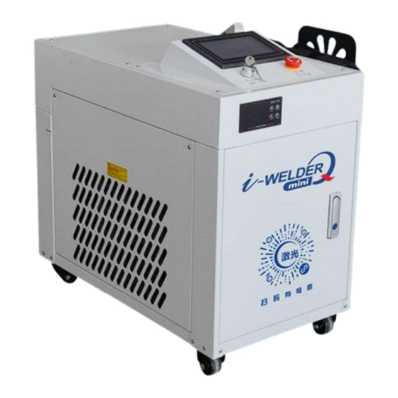
- Page 1 USER MANUAL FOR MINI Q WELDING/CLEANING MACHINE Model: ML-WF-BP-SCB-HW****...
-
Page 2: Table Of Contents
Table of Contents Copyright Notice ............................2 Certification Statement ..........................2 Welcome to User Manual ..........................2 Chapter 1 Safety ............................3 1.1 Safety Regulations ........................... 3 1.2 Safety Signs ............................. 4 Chapter 2 Equipment Introduction....................... 5 2.1 Overall Appearance and Structure......................5 2.2 Hand-Held welding gun. -
Page 3: Copyright Notice
3. The loss caused by natural forces makes the equipment in motion dangerous. The user is responsible for designing effective error handling and safety protection mechanisms outside of the equipment. Global Laser has no obligation or responsibility to be responsible for the incidental or corresponding losses or damages caused. -
Page 4: Chapter 1 Safety
Chapter 1 Safety 1.1 Safety Regulations When operating laser equipment, any mishap or improper action can pose significant danger. Operators must adhere strictly to the safety protocols for high-efficiency laser cleaning machines. This is essential not only for safeguarding individuals and equipment but also for ensuring optimal equipment functionality, achieving desired cleaning outcomes, and leveraging the equipment's processing advantages. -
Page 5: Safety Signs
1.2 Safety Signs Professional Beware of laser High voltage risk Laser Radiation Laser aperture maintenance CE Certificate Class IV laser Caution: Electricity High voltage warning Beware of Radiation Wear Protective Beware of static Beware of Ring position mask, glasses, Read instructions electricity airpressure gloves... -
Page 6: Chapter 2 Equipment Introduction
Chapter 2 Equipment Introduction. 2.1 Overall Appearance and Structure. Page | 5... - Page 7 Name Plate Power Switch Exhaust Fan Wire feeder Gas Input Power Page | 6...
- Page 8 S/no Description Parameters Equipment Name Handheld Fiber Laser Welding Machine Laser Power 500W, 800W, 1000W, 1500W, 2000W Collimation Focus Distance 60mm Focusing Focus Distance 150mm Protective Lens 20*3mm Laser Wavelength 1070 NM Fiber Length Standard 10M, Supports up to 15M Operating Mode Continuous / Modulated Welding Speed Range...
-
Page 9: Hand-Held Welding Gun
2.2 Hand-Held welding gun. Galvanomet Collimating Lens Reflective Focus Lens Laser Interface Protective Laser Trigger Lens Wire feeding mechanism. Page | 8... -
Page 10: Qbh Connection
2.3 QBH Connection The handheld laser welding gun fibre input interface (QBH). Before rotating the sleeve as depicted in the figure below, ensure that the red dot on the side of the sleeve aligns with the white dot on the coat. Rotate the sleeve to align with the red dot. - Page 11 3. Rotating Sleeve Alignment: a. Once the optical fiber head is inserted into the QBH, use your hand to gently press the rotating sleeve. b. Rotate the sleeve clockwise approximately 45 degrees until it is in position. c. Lift the rotating sleeve by hand until its bottom surface is flush with the top of the QBH. d.
- Page 12 2.4 Fine-tuning the polarization of the output beam spot. 1. Fine-tune the polarization both left and right. Screw Cover a. Remove the motor cover by taking out the two flat-head screws securing it. b. Loosen the hexagon machine meter screws on the fixing seat. By twisting the motor, you can make slight left and right adjustments.
-
Page 13: Replacing The Protective Lens
2.5 Replacing the protective lens. Protective lenses (both Screw positive and negative) Lock Lens pressure ring. plug seal 1. Removing and Sealing the Protective Mirror Drawer: a. Loosen the locking screws on the protective mirror drawer. b. Carefully remove the protective mirror drawer assembly. c. -
Page 14: Replacing The Collimating Lens
2.6 Replacing the collimating lens. M3 Screw M2 Screw 1. Releasing and Sealing the Collimating Lens Drawer Assembly: a. Loosen the M3 screws to release the collimating lens drawer assembly. b. Carefully remove the assembly once loosened. c. Seal the drawer cavity securely using self-adhesive tape. 2. -
Page 15: Replacing The Focusing Lens
3. Inspecting and Cleaning the Lens Surface: a. Inspect the lens surface for any dirt or debris. b. Use a dust-free cotton swab dipped in isopropyl alcohol to gently clean the lens if necessary. c. Replace the collimating lens with a new one, ensuring correct insertion into the collimating lens holder with attention to the plano-convex surface's orientation. - Page 16 Focus Protective Lens Lens Lens press plug seal Protective Focus Lens Lens Laser beam Page | 15...
-
Page 17: Replacing The Copper Nozzle
2.8 Replacing the copper nozzle. 1. Unscrew the copper nozzle from the connecting pipe by turning anti-clockwise. 2. Securely tighten the necessary copper nozzle onto the connecting pipe by turning it clockwise. Page | 16... -
Page 18: Chapter 3 Interface
Chapter 3 Interface 3.1 Powering On 1. Initial Power-Up and Login: a. Upon initial power-up and login, you'll encounter the device lock page b. You'll be prompted to decrypt the password for unlocking, utilizing the authorization code issued by the manufacturer. c. - Page 19 3. To extend the duration of the device's usage between expirations, follow these steps: a. Navigate to the IO port interface. b. Locate the decryption button positioned in the lower left corner. c. Click on the decryption button to activate a pop-up window. d.
-
Page 20: Login Screen
3.2 Login Screen Upon accessing the main page (as depicted in Figure 2-4), all operational keys on the screen remain inactive until logging in. To proceed, tap the user login button positioned in the lower left corner. Then, use the keypad within the red box to enter your login password. If an incorrect password is entered, a prompt will indicate the error, enabling you to correct the input and continue with the login process. -
Page 21: Password
3.4 Password Once you've logged in, proceed to the "Parameter Settings" and select the "Password Modification" page to change your password. Users with higher-level access can modify passwords for accounts with lower-level access. Passwords can consist of one to eight digits, but setting the password as '0' is not permitted. -
Page 22: Parameter Grouping
6. Laser Frequency: Determines the modulation frequency of the laser. Note: This parameter is inactive when the laser duty cycle is set to 100%. 7. Laser Duty Cycle: Represents the power output of the machine. A duty cycle of 100% indicates full power. -
Page 23: Changing Languages
3.7 Changing languages. In both the lock interface and parameter setting interface, you'll find language switch buttons available. Pressing this button will display a list of selectable countries for language switching. The available options in the list include Chinese, English, Korean, Italian, Romanian, and Polish. To exit the language selection list, simply click the switch language button again. -
Page 24: Io Port Interface
3.8 IO port interface On both the main page and the parameter setting page, there are buttons available to switch to the IO port screen. Clicking on this button grants access to the IO port screen, where you can observe all output signal lights. -
Page 25: Main
3.9 Main page interface In the upper right area of the main page, you can interact with or monitor the device status. The buttons within the red box are functional, except for the laser output button. 1. Safety Lock: Press and hold the laser button for 0.2 seconds to activate the safety lock. The indicator on the right illuminates, signaling that the laser is enabled. -
Page 26: Chapter 4 Lasers
Chapter 4 Lasers Operating the laser in environments below 10°C is restricted to prevent damage to its internal light source caused by condensation. This high-power laser device operates within the wavelength range of 1060nm to 1100nm, offering reliability, maintenance-free operation, and a water-cooled design with a photoelectric conversion efficiency exceeding 25%. -
Page 27: Environmental Requirements
4.2 Environmental requirements Condensation Temperature Chart Humidity 20% 25% 30% 35% 40% 45% 50% 55% 60% 65% 70% 75% 80% 85% 90% 95% Tempreture 16°C 18°C 21°C 24°C 27°C 29°C 32°C 35°C 38°C Note: The above picture depicts an environmental condensation point query table. The temperature at the intersection of temperature and humidity parameters represents the "Condensation Temperature"... -
Page 28: Chapter 5 Water Cooler
Chapter 5 Water Cooler Set the base temperature, upper limit, and lower limit temperatures of the water cooler unit. An alarm will activate if the temperature exceeds this predefined range. Monitor both the temperature gauge value and ambient temperature closely. The water cooler, as part of the laser welding machine's cooling system, circulates water to maintain optimal temperatures. -
Page 29: Chapter 6 Wire Feeder
Chapter 6 Wire Feeder Structure of the wire feeder Wire feeder interface Page | 28... -
Page 30: Introduction To The Main Functions
6.1 Introduction to the main functions 1. This wire feeder functions as an automatic driven mechanized wire feeding device. 2. Its lightweight design ensures simple operation. 3. Primarily utilized in laser handheld welding and automatic wire feeding applications. 4. The control system features microcomputer control, along with a high-precision fully enclosed low-speed motor and dual-drive wire feeding structure. - Page 31 Prior to usage, individuals must be knowledgeable about relevant safety equipment and equipped with necessary safety gear. 2. Wire feeder connection a. To connect the main body of the wire feeder with the wire outlet, use the wire feeding tube. Install the appropriate wire spool, ensuring that the copper nozzle on the wire tube is inserted into the correct position.
- Page 32 Adjustable preload pressure bar Wire tube Wire feed screw direction Wire feed wheels i. Begin by loosening the two adjustable preload pressure levers. ii. Next, loosen the two screws and remove the two wire feed wheels. iii. Replace the appropriate wire feeding wheel, ensuring that the side of the wire feeding groove corresponding to the specified specification and model faces inward.
-
Page 33: Chapter 7 Installation
Adjust the tightness of the wire feeding by twisting the two adjustable preload pressure rods left and right. Rotate the sleeve until the clamping force is appropriate for smooth and consistent wire feeding. Chapter 7 Installation 7.1 Installation Requirement The equipment should be installed in an independent space not less than 15m2 (depending on the actual supporting facilities). - Page 34 1. Connect the machine to the wall plug by attaching the 3-phase power cable to the socket. 2. Turn on the main power switch located at the back of the machine. 3. Switch on the machine using the key provided. 4.
-
Page 35: Shutting Down
7.3 Shutting down. 1. Turn off the laser key switch. 2. Deactivate the safety lock. 3. Turn off the machine key switch. 4. Switch off the main power by toggling the circuit breaker located behind the machine. 5. Close and turn off the gas supply. 6. - Page 36 4. Hold the hand-held gun head in the correct posture with the appropriate grip. Position your index finger next to the light switch. Press the switch to initiate welding when the gun head is properly aligned, indicated by the red light marking the laser's position. Maintain a constant speed while pushing forward or pulling back.
-
Page 37: Chapter 9 Equipment Safety Operation Procedures
When inserting the workpiece into the nozzle, it's common for the focal length to be off by a few millimeters. In such cases, adjust the extension length of the nozzle accordingly. Chapter 9 Equipment safety operation procedures 9.1 Safety operation procedures When the laser equipment is operational, any breakdown poses a significant danger. -
Page 38: Routine Checks
7. Handle protective gas cylinders carefully to avoid accidents. Adhere to gas cylinder safety regulations and avoid exposure to heat sources. Stand to the side when opening cylinder valves. 8. Immediately stop emitting laser and motion if any abnormality is detected during equipment operation to minimize damage. -
Page 39: Cleaning And Replacement Of Laser Protective Lens
9.3 Cleaning and replacement of laser protective lens During lens installation and cleaning, strict adherence to proper procedures is essential. Even the smallest speck of dirt, fingerprints, or oil droplets can impair the light transmittance of the lens, thereby reducing its service life and impacting the quality of laser processing. Therefore, the following precautions must be taken: 1. -
Page 40: Maintenance
4. Gently rub the mirror surface with a dry cotton swab in the same manner while the surface is still dry. 5. If necessary, repeat the process until satisfied, using new cotton swabs each time. 6. For stubborn water stains, use a mixture of absolute ethanol and absolute ether for final treatment. - Page 41 Unscrew out the sealing cap before adding water. 2. Filter Cleaning a. Regularly clean the dust filters located on the sides and front of the cabinet to ensure proper ventilation and heat dissipation. 3. Cleaning the welding nozzle a. Extended use of the tip of the nozzle can lead to the accumulation of slag, obstructing the flow of shielding gas and affecting the laser energy delivered to the material surface.
Need help?
Do you have a question about the MINI Q and is the answer not in the manual?
Questions and answers