Table of Contents
Advertisement
Quick Links
Advertisement
Table of Contents

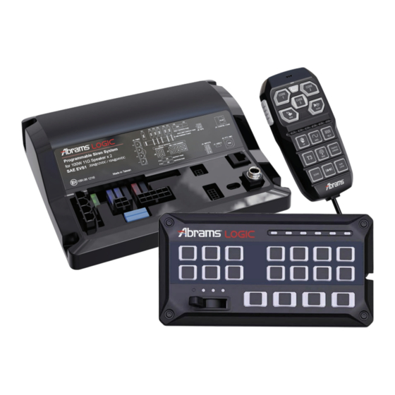
Summary of Contents for Abrams LGS-2200-H
- Page 1 LGS 2200 H/C SIREN AMPLIFIER SOFTWARE MANUAL Rev.2 190723...
-
Page 2: Table Of Contents
Table of Contents Chapter 1: Getting Started 1-1 Minimum System Requirements ………………….………….…………………………….…………………….… 3 1-2 Installation …………………….…….………………….……….…………………………….…………………….… 3 1-3 Hardware Condition Check …………………….…….……….…………………………….…………………….… 4 1-4 Overview / Create New Configuration……………….……….…………………………….…………………….… 5 Chapter 2: Main Interface 2-1 Interface Overview ……………………………..………………………………………………….……………..…… 7 2-2 Menu Bar ……….…..…………………………….…..……………………………………….………………………8 2-3 General Setting …………..…..……………………….………………..…………..……………………………….. -
Page 3: Chapter 1: Getting Started
Chapter 1: Getting Started 1-1. Minimum System Requirements CPU: 1 GHz Processor or higher. RAM: 1 GB RAM. HDD: 40MB available space. Microsoft Windows® 7, Windows 8/8.1, and Windows 10 Screen Resolution: 1024 x 768 or higher (Recommend Resolution 1920 x 1080). Others: .NET Framework 4.5 1-2. -
Page 4: Hardware Condition Check
1-3. Hardware Condition Check When starting LGS-2200 Siren Configuration Tool, the software will check current hardware condition. You may confirm the connectivity in this page or continue without checking. Driver Check If applicable driver is not yet installed, [INSTALL DRIVER] button will be shown. User must first connect the Siren Unit to the PC via a USB cable, and then click [INSTALL DRIVER] to install the driver for the controller module. -
Page 5: Overview / Create New Configuration
1-4. Overview / Create New Configuration ② ① ③ ② ① ③ Choose Your Control Panel Select your control panel model. The selected control panel style must match your actual unit. Fail to match the correct panel style may result in siren unit not functioning to the setting or unable to function correctly. - Page 6 Amplifier Firmware Label Controller Firmware Label Controller Firmware Label...
-
Page 7: Chapter 2: Main Interface
Chapter 2: Main Interface 2-1. Interface Overview ① ② ⑤ ③ ④ ② ① ⑤ ③ ④ Menu Bar Contains basie file options such as create new, save, etc. (see Chapter 2-2). General Setting Click on Gear Icon to change the properties of the general setting (see Chapter 2-3). -
Page 8: Menu Bar
2-2. Menu Bar ③ ④ ⑤ ① ② Create New Configuration Click to re-start with a new configuration and setting. (see Chapter 1-4) Open Existing Configuration Click to select an existing configuration and setting file (.sdp2) from the host PC. ... -
Page 9: General Setting
2-3. General Setting ① ② ③ ④ ⑤ General Setting Click the Gear Button at the top right of the window to set general setting. The current selected controller firmware version is also shown here. Button Backlight Default ... -
Page 10: Chapter 3: Button/Input And Profile
Chapter 3: Button/Input and Profile 3-1. Panel Button and Other Inputs ① ① ② Controller Panel Push-Buttons Each button can hold an OFF profile and one to four ON profile(s). By default, all Push Button start-up in OFF profile upon restart. ... -
Page 11: Profile Setting
Other Inputs Load Management This Load Management can hold an OFF profile and one to four ON profile(s). It detects current main input power voltage and changes its profile based on that voltage value. This input is often used for battery low voltage protection. ... -
Page 12: Chapter 4: Settings And Variables
Chapter 4: Settings and Variables 4-1. Overview ① ② ③ ④ ⑤ Properties Change settings of each button / function wire input (see Chapter 4-2). Inputs Chapter 4-3). Change Input actions for each Profile state of each button / wire input (see ... -
Page 13: Button Mode
③ Trigger VOLT (available on selective inputs only) [VOLT+]: Trigger this input wire by Positive (+VDC) Switching. [VOLT-]: Trigger this input wire by Negative (GROUND) Switching. ④ Button Mode Each button/input is designated a "button mode". Its operation and setting variables are based on the button mode. - Page 14 [Record-n-Play]: Use for recording and playing a short message through the siren speaker (up to 20 seconds) Can only hold an OFF and one ON profile. Can only be set to Long Record, Press Play. Only one button or one wire may be set to this Mode. ...
-
Page 15: Off Delay
⑤ ⑥ ⑦ Profile Cycle NOTE: Only available when “Double Press Off” or “Hold Off” switch type is selected. [One Way] Profile will progress in OFF > ON > ON2 > ON3 > ON4 (whenever applicable). Unless amended by other means (e.g. other button or input action), profile does not cycle back to OFF profile. -
Page 16: Switch Type
⑨ Switch Type Each button can be set as one of the following switch types: [Disabled]: Disable this button and turn off all functions activated by this button. [Press On, Release Off] [Press On, Press Off] ... -
Page 17: Input Actions
4-3. Input Actions Each profile offer a set of actions to amend the status of other inputs upon the activation of the profile. ① ② [Controller Panel] and [Other Input] Select to show the list of Buttons or Other Inputs. ... -
Page 18: Output Actions
4-4. Output Actions Each profile can select a set of actions for the Wire Output and Controller LEDs throughout the duration of the activation of the profile. ② ③ ① Wire Output Each profile may select a set of actions to turn ON or OFF for each OUTPUT throughout the duration of the activation of the profile. - Page 19 Backlight Each button / input, regardless of the number of profiles, can store an override Backlight brightness for the controller. The brightness will be applied throughout the duration of the activation of its ON profile. Check Box: Check to allow overriding of brightness on this button / input. ...
-
Page 20: Tone Actions
4-5. Tone Actions Based on the button mode, the available Tone Actions may be different. ① ② ④ ③ Siren Speaker Select the desired action for the two speaker output. [None]: Does not perform any action; disregard any selected tone in Tone Setting. ... -
Page 21: Tone Setting
Tone Setting Based on the button mode, the available Tone Actions may be different. [General]: a. Primary Tone Select a Tone to be broadcasted when activated. b. Override Tone Select a Tone to be broadcasted when activated with “Tone Change” function (i.e. MAN or Horn-Ring Transfer button/input). - Page 22 c. Siren Tone Change Select a Tone Change method for activating Override Tone. None Does not active Override Tone Press On, Press Off Press to activate Override Tone, press again to revert back to Primary Tone. Press On, Release Off Press to activate Override Tone, release to revert back to Primary Tone.
- Page 23 [Hand-Free]: a. End Method Select an action method to end Hand-Free Siren Tone. Cycle End Turns OFF when all tones have been cycled through. Double Press End Double press to OFF. b. Volume Set a broadcast volume for this button/input. c.
- Page 24 [Volume Adj.]: a. Adjusting Volume Select a style when changing volume. Volume Down Decrease a volume step when pressed. Volume Up Increase a volume step when pressed. b. Adjusting Step Select a volume step when pressed. 5% ...
-
Page 25: Chapter 5: Priorities
Chapter 5: Priorities 5-1. Priorities Set the order of precedence for all the buttons and inputs. When more than one button / input are activated at the same time, all active inputs / profile actions will perform their functions (or not) based on the order of precedence. Lower precedence actions will be overridden. ①... - Page 26 b. Change the precedence of the selected button / input by using the arrows on the right Move to the top Move up Move down Move to the bottom...
-
Page 27: Appendix A. Copyright Notices
All rights reserved. Under the copyright laws, this manual may not be copied, in whole or in part, without the written consent of Abrams. Abrams reserves the right to change or improve its products and to make changes in the content of this manual without obligation to notify any person or organization of such changes or improvements.
Need help?
Do you have a question about the LGS-2200-H and is the answer not in the manual?
Questions and answers