
Related Manuals for Images SI PAS-01K

Summary of Contents for Images SI PAS-01K
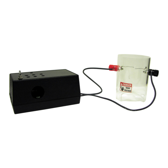
- Page 1 Images SI, Inc. 109 Woods of Arden Road Staten Island NY 10312 718.966.3694 Tel 718.966.3695 Fax http://www.imagesco.com Pl asm a Ar c Sp e ak e rKi t PAS-01K See high voltage safety guide pg 3...
-
Page 2: Table Of Contents
M anual and C ons t ruc t i on B ooklet For P las m aA rc Sp eaker Ki t Tab le ofC ont ent s Safet y Gui d eli nes ..... . 3 W arrant y. -
Page 3: Safet Y Gui D Eli Nes
H i g h V olt ag e Safet y The plasma arc speakers are high voltage devices. If you are not familiar with work- ing with high voltage devices we do not recommend you build this device. While this high voltage it is not necessarily lethal. A person’s health has an impact on the amount of current that could be lethal. -
Page 4: Warranty
14) Do not add, substitute or remove components to the kit assembly. WARRANTY IF YOU DO NOT AGREE TO THESE CONDITIONS, YOU SHOULD NOT PURCHASE THE PRODUCT. IN NO EVENT SHALL IMAGES SI BE LIABLE FOR ANY INCIDENTAL, SPECIAL, CONSEQUENTIAL OR PUNITIVE DAMAGES, OR FOR ANY COSTS, ATTORNEY FEES, EX-... -
Page 5: B Ac Kg Round I Nform At I On
B ac kg round I nform at i on Plasma, as it is referred to herein, is a high temperature highly ionized gas. (Not the plasma as in "blood plasma") Plasma is considered the fourth state of matter, after solid, liquid and gas. It is the most abundant state of matter in the known universe. -
Page 6: C Om M Erc I Ala P P Li C At I Ons
an oxygen-acetylene torch to create a high temperature flame. Cooler flames from a propane torch could be used, but needed to be seeded with an easily ionized material such as potassium nitrate to generate a useable amount of low temperature ions. Seeding also increased the volume output of the high temperature flame speakers. -
Page 7: H Ow I T W Orks
H ow i t w orks Many published schematics on building a plasma arc speaker on the internet use either a 555 Timer or TL494 PWM Controller. There are many varia- tions of these circuits depending upon the high voltage transformer used. I choose to use the 555 Timer for my design. -
Page 9: C Ons T Ruc T I On
C i rc ui t C ons t ruc t i on The schematic for the Plasma Arc Speaker is shown in Figure 1. The top silkscreen of the PCB is shown in Figure 2, above. All components are mounted and soldered to the top of the PCB. Before beginning construction, it is important to review the HV Guidelines included on page 3 of this manual. - Page 10 Now attach the Heatsink to the high voltage transistor using the included screw and nut. Insert the transistor at Q2 with it facing the 8 pin socket. Sol- der the transistor and heatsink into place. Next mount and solder the remaining capacitors. C6 is a .1uf, Capacitor. Take note of the polarization marked on the silkscreen for C1, C4 and C5.
-
Page 11: A S S Em B Li Ng T He P Las M Atub E
lead above the PCB, solder into place. Figure 4 shows an overhead view of the completed circuit. A s s em b li ng t he P las m aTub e Completely remove the insulation from the single stranded wire included in the kit. -
Page 12: A Ud I O I Np Ut
A ud i o I np ut W arni ng ab out A ud i o P layb ac k Devi c es : There is always a chance that the high voltage could jump to the low volt- age side of the device and damage the audio player device. Use audio de- vice at your own risk. -
Page 13: C As I Ng T He Uni T
Before turning on the circuit, adjust the electrodes as shown in Figure 6. Notice how the ends of the wire are arc so that the ends of each wire face the opposite wire end. This is to insure the arc forms between the wire ends, which will provide the best audio quality. - Page 14 case and secure with included screws through the holes in the bottom of the case. Reattach the HV wires to the binding posts and the unit is now ready to be used. Two high voltage labels have been included with this kit. One should be placed on the Plasma Tube;...
- Page 15 A p p end i x A Determining Resistor Values: Resistor values are read using the color bands on the body of the resistor. The first band is the one nearest the end of the resistor. Start reading from this band. The first band represents the first significant number, the second band, the second significant number and the third band is the multiplier.
-
Page 16: P Art S L I S T
P A S-01 P art s L i s t Location Part Number PCB-PAS HVT-01 (Transformer) PJ-102A (power jack) SW-10 (toggle switch) RES-100-120K RES-100K R2 R5 R7 RES-10K RES-1K POT-25K-multi (can use 10K-25K) - (1) CAP-470uf-25V (can use 470-1000uf, 16V or higher) - (1) CAP-.001uf, 100V CAP-330pf-50V C4 C5...
Need help?
Do you have a question about the PAS-01K and is the answer not in the manual?
Questions and answers