Table of Contents
Advertisement
Quick Links
Advertisement
Table of Contents

Related Manuals for TEXAS RANGER TRE-936FFB

Summary of Contents for TEXAS RANGER TRE-936FFB
- Page 1 TRE-936FFB 40 Channel AM Mobile CB Radio Owner's Manual...
-
Page 2: Table Of Contents
CONTENS PAGE Specifications ........Installation ........Location . -
Page 3: Specifications
SPECIFICATIONS GENERAL Model TRE-936FFB Channels Frequency Range 26.965 ~ 27.405 MHz Emission Frequency Control Phase-Lock-loop (PLL) Synthesizer Frequency Stability 0.001% Temperature Range -30C to +50C Antenna Impedance 50 Ohms Antenna Connectors Standard SO-239 type Input Voltage 13.8V DC 7- 3/8” (W) x 8- 3/4” (D) x 2- 1/4” (H) -
Page 4: Installation
INSTALLATION LOCATION Plan the location of the transceiver and microphone bracket before starting the installation. Select a location that is convenient for operation and does not interfere with the drive or passengers in the automobiles, the transceiver is usually mounted the dash panel with the microphone bracket beside it. -
Page 5: Ignition Noise Interference
INSTALLATION IGNITION NOISE INTERFERENCE Use of a mobile receiver at low signal levels is normally limited by the presence of electrical noise. The primary source of noise in automobile installation is from the generator and ignition system in the vehicle. Under most operating conditions, when signal level is adequate, the background noise does not present a serious problem. -
Page 6: Tuning The Antenna For Optimum Swr
INSTALLATION TUNING THE ANTENNA FOR OPTIMUM S.W.R Since there is such a wide variety of a base and mobile antenna, this section will strictly concern itself to the various types of mobile adjustable antennas. Because the antenna length is directly related to the channel frequency, it must be tuned to resonate optimally on all channels of the transceiver. -
Page 7: External Speaker
INSTALLATION If you’re having difficulties in adjusting your antenna, check the following: All doors must be closed when adjusting the antenna Make sure the antenna base is grounded. Check your coaxial cable routing (it may be pinched when routed into the car) Try a different location in your car (keeping in mind the radiation pattern you wish.) Is the antenna perfectly vertical? Try a different location in your neighborhood. -
Page 8: Operation
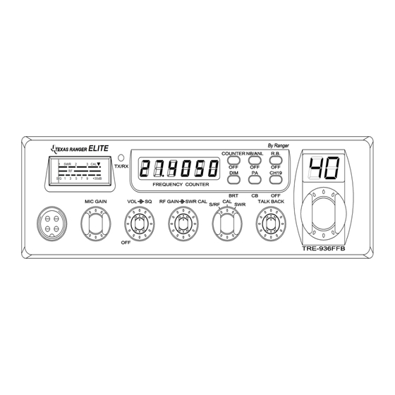
OPERATION FRONT PANEL 1. MICROPHONE JACK: Used to connect microphone for voice source. 2. MIC GAIN CONTROL: Adjust the microphone gain in the transmit and PA modes. This controls the gain to the extent that full talk power is available several inches away from the microphone. - Page 9 OPERATION 5. RF GAIN CONTROL: This control is used to reduce the gain of the RF amplifier under strong signal conditions. 6. SWR CAL CONTROL: This SWR CAL control allows the user to calibrate the SWR meter. 7. S-RF/CAL/SWR SWITCH: In the S-RF position, the meter will indicate the strength of the signal being received, as well as the relative RF output of transmission.
-
Page 10: Rear Panel
OPERATION 17. ROGER BEEP SWITCH: When this switch is placed in the ROGER BEEP position, the radio automatically transmits an audio tone at the end of your transmission. This indicates the end of your transmission so that people who are having trouble hearing you will know that you are done speaking. -
Page 11: Frequency Chart
OPERATION FREQUENCY CHART Channel Channel Frequency Channel Channel Frequency 26.965 MHz 27.215 MHz 26.975 MHz 27.225 MHz 26.985 MHz 27.255 MHz 27.005 MHz 27.235 MHz 27.015 MHz 27.245 MHz 27.025 MHz 27.265 MHz 27.035 MHz 27.275 MHz 27.055 MHz 27.285 MHz 27.065 MHz 27.295 MHz 27.075 MHz... -
Page 12: Procedure To Receive And Transmit
OPERATION PROCEDURE TO RECEIVE AND TRANSMIT A. MICROPHONE The receiver and transmitter are controlled by the push-to-talk switch on the microphone. Press the switch and the transmitter is activated, release switch to receive. When transmitting, hold the microphone two inches from the mouth and speak clearly in a normal voice. -
Page 13: Alternate Microphone And Installation
OPERATION ALTERNATE MICROPHONES AND INSTALLATION For best results, the user should select a low-impedance dynamic type microphone or a transistorized microphone. Transistorized type microphones have low output impedance characteristics. The microphones must be provided with a four-lead cable. The audio conductor and its shielded lead comprise two of the leads. - Page 14 OPERATION Before beginning the actual wiring, read carefully the circuit and wiring information provided with the microphone you select. Use the minimum heat required in soldering the connections. Keep the exposed wire lengths to a minimum to avoid shorting when the microphone plug is reassembled.
- Page 15 OPERATION 5. The wires must now be soldered to the pins as indicated in the above wiring tables. If a vise or clamping tool is available it should be used to hold the pin receptacle body during the soldering operation, so that both hands are free to perform the soldering. If a vise or clamping tool is not available, the pin receptacle body can be held in a stationary position by inserting it into the microphone jack on the front panel.
-
Page 16: Maintenance And Adjustment
OPERATION 9. The two cable clamp retainer screws should now be tightened to secure the housing to the microphone cord. If the cutting directions have been carefully followed, the cable clamp should secure to the insulation jacket of the microphone cable. 10. -
Page 17: A Few Rules That Should Be Obeyed
OPERATION A FEW RULES THAT SHOULD BE OBEYED You are not allowed to carry on a conversation with another station for more than five minutes at a time without taking a one-minute break, to give others a chance to use the channel. - Page 18 Memo - 17 -...
- Page 19 Memo - 18 -...
- Page 20 - 19 -...
- Page 21 - 20 -...
Need help?
Do you have a question about the TRE-936FFB and is the answer not in the manual?
Questions and answers