
Summary of Contents for Securitron MR-2312-AT Series
- Page 1 MR-2312-AT Series Remote Multiplex Annunciator Panel A.C. COMMON SIGNAL TROUBLE SILENCED BUZZER SIGNAL SILENCE SILENCE LAMP SYSTEM TEST RESET LT-658SEC Rev. 3 Wiring and Installation Manual July 2023...
-
Page 3: Table Of Contents
Table of Contents Introduction Installation Instructions Controls and Displays ....................Wiring Instructions DIP Switch Settings Jumper Selection ......................Specifications and Features Enclosure ........................Electrical Specifications ....................Current Drain for Battery Calculations ................Environmental Specifications ..................Warranty and Warning Information... -
Page 4: Introduction
Introduction Secutron’s MR-2312-AT Annunciator is a 16-circuit annunciator for use with Secutron’s MR- 2300 Series Fire Alarm Control Panels. Annunciators mount into the MMX-BB-1001D enclosure, and may not be expanded. Control access is by a keyswitch. Each circuit indicator is a bi-colour LED that is automatically configured to match the fire alarm control panel configuration. -
Page 5: Installation Instructions
Installation Instructions Table 1 Enclosure Dimensions and Capacity Height Mounting Mounting Annunciator Enclosure Model Number Width (in.) H(in.) A (in.) B (in.) Capacity MMX-BB-1001D / MMX-BB-1001DR / MMX- 9.0” 12.75” 9.95” 7.5” BB-1001DB / MMX-BB-1001DS Note: No suffix R is for white door. Suffix R is for red door. -
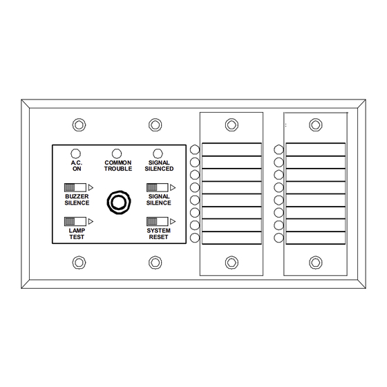
Page 6: Controls And Displays
BB-1001D Annunciator Assembly 4 nuts Figure 2 Secure annunciator assembly to MMX-BB-1001D enclosure Notes: The MR-2312-AT is supplied with NP-386 paper labels for zone identification. This annunciator displays initiating circuit status only (no individual circuit troubles). Indicating and relay circuits are not remotely displayed. For more details, refer to the manual of the fire alarm control panel that the annunciator will be connected to. -
Page 7: Wiring Instructions
Wiring Instructions The RS-485 Wiring to the MR-2312-AT Module is recommended to be 24 VDC POWER TO 24 VDC NEXT ANNUNCIATOR OUTPUT twisted shielded pair as shown in the diagram. The wire gauge may be: 24 VDC 24 VDC POWER FROM FIRE ALARM CONTROL INPUT PANEL OR PREVIOUS ANNUNCIATOR •... - Page 8 Table 3 Maximum Wiring Run to Last Annunciator Total Maximum Current Maximum Loop for all Annunciators Resistance 18AWG 16AWG 14AWG 12AWG Amperes Ohms 0.12 1180 1850 3000 4250 1296 0.30 1200 1900 0.60 0.90 1.20 1.50 1.70...
-
Page 9: Dip Switch Settings
DIP Switch Settings Each annunciator needs to be assigned a unique, sequential address via DIP switches SW1- 1, SW1-2, and SW1-3. DIP switch SW1-4 is used to allow disabling of some front panel slide switches. SW1-1 Address A0 Three digit address of the annunciator (address SW1-2 Address A1 range 1 to 7 inclusive) -
Page 10: Specifications And Features
Specifications and Features Enclosure • A standard 4-gang electrical box is used. Electrical Specifications • 24 VDC nominal voltage • Slide-switch controls, LED indicators, and keyswitch to enable controls. • Local buzzer, indicators (ac-on, common trouble, signal silence), and controls (system reset, lamp test, buzzer silence, signal silence). -
Page 11: Warranty And Warning Information
Warranty and Warning Information WARNING! Please read this document CAREFULLY, as it contains important warnings, life-safety, and practical information about all products manufactured by the Mircom Group of Companies, including Mircom and Secutron branded products, which shall include without limitation all fire alarm, nurse call, building automation and access control and card access products (hereinafter individually or collectively, as applicable, referred to as “Mircom System”). - Page 12 The testing should include all sensing devices, keypads, consoles, alarm indicating devices and any other operational devices that are part of the system. NOTE TO USERS: All Mircom Systems have been carefully designed to be as effective as possible. However, there are circumstances where they may not provide protection.
-
Page 13: Warranty
13. Wireless Devices Placement Proximity. Moreover all wireless devices must be a minimum and maximum distance away from large metal objects, such as refrigerators. You are required to consult the specific Mircom System manual and application guide for any maximum distances required between devices and suggested placement of wireless devices for optimal functioning. - Page 14 CANADA - Main Office U.S.A © Secutron 2023 25 Interchange Way Printed in Canada 4575 Witmer Industrial Estates Subject to change without prior notice Vaughan, ON L4K 5W3 Niagara Falls, NY 14305 Tel: (905) 660-4655 Tel: (905) 660-4655 www.secutron.com (888) 660-4655 (888) 660-4655 Fax: (905) 660-4113 Fax: (905) 660-4113...
Need help?
Do you have a question about the MR-2312-AT Series and is the answer not in the manual?
Questions and answers