Table of Contents
Advertisement
Quick Links
Advertisement
Table of Contents

Summary of Contents for Manusa Optima V2
- Page 1 Installation manual Optima V2 program switch...
-
Page 2: Table Of Contents
Installation manual / Manusa DTCXSO01EN-V10 Manusa Table of Contents 1. Description 2. Selecting door operating mode 3. Technical specifications 4. Wiring 5. Optima Selector Configuration as V1 or V2 5.1 Check Optima Selector Configuration Status 5.2 Change Optima Selector Configuration State 6. -
Page 3: Description
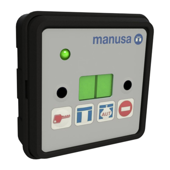
Installation manual / Manusa DTCXSO01EN-V10 1. Description Control element that, when connected to a VISIO, ACTIVA+, VISIO+ or BRAVO operator, enables selection of door operating mode, access to Technical Service functions, and fault display. Two different combinations of keys enable keypad locking and unlocking. -
Page 4: Technical Specifications
Installation manual / Manusa DTCXSO01EN-V10 3. Technical specifications Technical specifications 10 mm Height of 7-segment display 38 kHz Infrared receiver frequency Average reach of remote control 12 VCC Power supply 120 mA Consumption 0–50 ºC Ambient operating temperature 75 x 75 x 53 mm... -
Page 5: Optima Selector Configuration As V1 Or V2
Once connected, one of the following options appears on the screen: elector is configured as Selector Optima V1 the selector is configured as Selector Optima V2. (default) 5.2 Change Optima Selector Configuration State To change the configuration status between “u1” and “u2” it is done in the following steps: Disconnect power from the Optima Selector. -
Page 6: Accessing Technical Service Functions
Installation manual / Manusa DTCXSO01EN-V10 6. Accessing Technical Service functions To access Technical Service functions, follow the instructions below. Press and hold key (3) and press key (2) repeatedly until F0 is displayed. Release key (3). Press (2) repeatedly for the functions to be shown in sequence on the display. -
Page 7: Selecting Language
Installation manual / Manusa DTCXSO01EN-V10 Press (2) repeatedly until F8 appears. Then press (3). Once set, check correct operation of safety elements: photocells, radars, etc. Note: For Visio and Bravo operators, ensure the leaves are closed before starting the self-adjustment procedure. -
Page 8: Adding Remote Controls To The Authorised List
Installation manual / Manusa DTCXSO01EN-V10 6.5 Adding remote controls to the authorised list When remote controls are used for the first time, the list must be deleted as shown in section 5.6. Press (2) repeatedly until FC appears. Then press (3). -
Page 9: Advanced Settings
Installation manual / Manusa DTCXSO01EN-V10 7. Advanced settings To access the advanced settings submenu, first access the FD service function. Numerical parameters are adjusted in the same way as Technical Service functions (see section 5.1). Safety self-adjustment. (1) Begin self-adjustment, (0) exit submenu without making any changes. -
Page 10: Setting Admin And User Passwords
Installation manual / Manusa DTCXSO01EN-V10 8. Setting admin and user passwords To access the advanced settings submenu, first access the FD service function. Numerical parameters are adjusted in the same way as Technical Service functions (see section 5.1). Setting admin password Length of admin password and factory default The admin password must contain between 4 and 8. -
Page 11: Warning Messages
Installation manual / Manusa DTCXSO01EN-V10 10. Warning messages When the automatic door operator detects a door malfunction, the program switch screen will show a numeric code. The meaning of the code is summarised in the table below. Depending on the operator, sometimes the code numbers may be different. -
Page 12: Wi-Fi Connection Status
Installation manual / Manusa DTCXSO01EN-V10 Warning Fault Possible cause Corrective action Critical alarm. Possible internal electronics Contact Manusa Technical Service. failure. Change electronics. Critical alarm. Possible internal electronics Contact Manusa Technical Service. failure. Change electronics. Critical alarm. Possible internal electronics... - Page 13 The characteristics described in this document are purely informative and are in no way binding. The manufacturer reserves the right to make modifications without prior notice. Via Augusta, 85-87, 6th floor · 08174 Sant Cugat del Vallès (Barcelona) · Spain manusa@manusa.com · +34 93 591 57 00 · www.manusa.com...
Need help?
Do you have a question about the Optima V2 and is the answer not in the manual?
Questions and answers