Advertisement
Quick Links
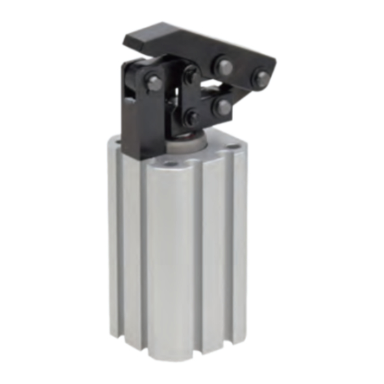
P n eu ma tic Link Clamp
- Re trac ting M od el-
W F C
M od e l
Larger Size Added: model WFC0320 (Cylinder Inner Diameter 32mm)
Lever Retracted to Avoid Interference
during Workpiece Loading/Unloading
Compact Body and Compact Lever Movement
F ea t ur e s
Lever Retracted Lower than the Clamping Point
Large lever retraction allows for wide angle of loading and unloading workpieces between operations.
Enables to Clamp Difficult Clamping Points
The compact lever-operating range enables to clamp difficult clamping points.
Excellent Coolant Resistance
Our exclusive dust seal is designed to protect against high pressure coolant. It also has high durability
against chlorine-based coolant by using a sealing material with excellent chemical resistance.
Standard Lever is also Available as an option
1
Avoid Interference
Avoid Interference
during Transfer
during Transfer
Released (Loading)
Workpiece
WFC
Clamped
No
Interference
Work
piece
Clamping Point
Advertisement

Summary of Contents for kosmek WFC0200-C Series
- Page 1 P n eu ma tic Link Clamp - Re trac ting M od el- W F C M od e l Larger Size Added: model WFC0320 (Cylinder Inner Diameter 32mm) Lever Retracted to Avoid Interference during Workpiece Loading/Unloading Compact Body and Compact Lever Movement F ea t ur e s Lever Retracted Lower than the Clamping Point Large lever retraction allows for wide angle of loading and unloading workpieces between operations. Clamping Point Avoid Interference Avoid Interference during Transfer during Transfer Released (Loading) Clamped Enables to Clamp Difficult Clamping Points The compact lever-operating range enables to clamp difficult clamping points.
- Page 2 Action Action Model No. Performance External Lever Design Features Features Specifications Cautions Dimensions Dimensions Description Description Indication Curve Action Description Released State Locked State Workpiece Lever Dust Seal Release Port Piston Rod Magnet Lock Port 2-Positioning Pin (Included) When air is applied to the release port. When air is applied to the lock port. A p p l i c a t i o n Ex a mp le For ...
-
Page 3: Auto Switch
NPN Output S-Pole Sensor ※2 Non-Contact : ※1 ※3 High-Accuracy JES0000-02GPS ※2 PNP Output S-Pole Sensor Sensor for 3-Wire IP67 L Shaped Non-Contact : Air Cylinder JES0000-02LGS ※2 NPN Output S-Pole Sensor Non-Contact : JES0000-02LGPS PNP Output S-Pole Sensor ※2 Notes : 1. For further information, refer to the product catalogs of Auto Switch (JEP) and High-Accuracy Sensor for Air Cylinder (JES) on our website. When using an auto switch not made by Kosmek, check specifications of each manufacturer. 2. Auto Switch / High-Accuracy Sensor for Air Cylinder may be stuck out of the link clamp depending on the installation position and direction. ※1. The detection range of High-Accuracy Sensor for Air Cylinder (JES) is different from that of Auto Switch (JEP), and even small stroke can be securely detected by JES. Refer to “Performance Curve” on the JES catalog for further information. ※2. When detecting both lock and release positions with High-Accuracy Sensor for Air Cylinder (JES), please use two S-pole sensors. ※3. JEP/JES series cannot be used in an environment which generates a magnetic field disturbance. Please use D-P3DWA (manufactured by SMC) for those environments. -
Page 4: Specifications
Action Action Model No. Model No. Performance External Lever Design Features Features Specifications Specifications Cautions Dimensions Dimensions Description Description Indication Indication Curve Model No. Indication W FC 0 20 0 - C A Cylinder Inner Diameter : Cylinder Inner Diameter = φ20mm : Cylinder Inner Diameter = φ32mm Design No. 0 ... - Page 5 Pneumatic Link Clamp -Retracting Model- W FC m o d e l Clamping Force Curve L : Lever Length (mm) (How to Read the Clamping Force Curve) F : Clamping Force (N) In case of WFC0200: When supply air pressure is 0.5MPa and lever length L is 35mm, clamping force becomes about 78N. Work P: Supply Air Pressure (MPa) piece Notes : ※1. F:Clamping Force (N), P:Supply Air Pressure (MPa), L:Lever Length (mm). Cylinder force (When L=0) cannot be calculated from the calculation formula of clamping force. 1. The table and graph show the relationship between the clamping force (kN) and supply air pressure (MPa). 2. Values in the chart indicate clamping force when the lever locks a workpiece in horizontal position. 3. The clamping force varies depending on the lever length. Set the suitable supply air pressure based on the lever length. 3739×P Clamping Force ※1...
- Page 6 Action Action Model No. Model No. Performance External Lever Design Features Features Specifications Specifications Cautions Dimensions Dimensions Description Description Indication Indication Curve MEMO...
- Page 7 Pneumatic Link Clamp -Retracting Model- W FC m o d e l External Dimensions:WFC0200-C□ ※ The drawing shows the locked state of WFC0200-CA. □30 □20 ※1 Lever Option:A Lever Option:Blank Lever (Prepared by Customer) φ8 φ15 14.4 Release Port M5×0.8 Thread Depth 4 (M4×0.7 Thread) Lock Port M5×0.8 Thread Depth 4 (φ6g7) 2- Positioning Pin (Included) 4 -φ6 ±0.02 ±0.02 -0.004 (Mounting Hole of Outer Diam. : φ6g7 -0.016 Positioning Pin) (Recommended to use 2 parts diagonally.)
- Page 8 Action Action Model No. Model No. Performance External Lever Design Features Features Specifications Specifications Cautions Dimensions Dimensions Description Description Indication Indication Curve Lever Design Dimensions for WFC0200 ※ Reference for designing link lever for WFC0200. + 0.012 2-φ4H7 0 ±0.05 45° R2.25 Notes : 1. Please design the link lever length according to the performance curve on P.5. 2. Use the attached pin (equivalent to φ4f6, HRC60) as the lever mounting pin.
- Page 9 Pneumatic Link Clamp -Retracting Model- W FC m o d e l External Dimensions:WFC0320-C□ ※ The drawing shows the locked state of WFC0320-CA. ※1 Lever Option:A Lever Option:Blank 49.5 Lever 17.5 (Prepared by Customer) φ 10 φ 18 Release Port M5×0.8 Thread Depth 4 Lock Port (M5×0.8 Thread) M5×0.8 Thread Depth 4 (φ7.5g7) 2- Positioning Pin (Included) 4 -φ7.5 ±0.02 ±0.02 -0.005 Outer Diam. : φ7.5g7 -0.020 (Mounting Hole of ...
- Page 10 Action Action Model No. Model No. Performance External Lever Design Features Features Specifications Specifications Cautions Dimensions Dimensions Description Description Indication Indication Curve Lever Design Dimensions for WFC0320 ※ Reference for designing link lever for WFC0320. +0.012 ±0.05 17.5 2-φ5H7 0 45° 28.5 Notes : 1. Please design the link lever length according to the performance curve on P.5. 2. Use the attached pin (equivalent to φ5f6, HRC60) as the lever mounting pin.
- Page 11 Pneumatic Link Clamp -Retracting Model- W FC Cautions m o d e l Cautions ● Notes for Design 1) Check Specifications 6) When using in a dry environment ● Please use each product according to the specifications. ● The link pin can be dried out. Grease it up on a regular basis. 2) Notes for Circuit Design 7) Protective Cover Installation ● Ensure there is no possibility of supplying air pressure to the lock ● If the moving parts of the cylinder may endanger human life, port and the release port simultaneously. Improper circuit design please install the protective cover. may lead to malfunctions and damages. 8) Speed Adjustment 3) Notes for Link Lever Design ● If the clamp operates too fast, the parts will be worn out and ● ...
- Page 12 Action Action Model No. Model No. Performance External Lever Design Features Features Specifications Specifications Cautions Dimensions Dimensions Description Description Indication Indication Curve ● Installation Notes 1) Check the Usable Fluid 4) Installation / Removal of the Link Lever ● Please supply filtered clean dry air. ● When inserting a link pin, do not hit the pin directly with a hammer. ● Oil supply with a lubricator etc. is unnecessary. When using a hammer to insert the pin, always use a cover plate If oil is supplied with a lubricator, etc., the operation under low with a smaller diameter than the spring ring groove on the pin. pressure and low speed may be unstable. (When using lubricant, please supply lubricant continuously.) 2) ...
- Page 13 Pneumatic Link Clamp -Retracting Model- W FC Cautions m o d e l Cautions ● Notes on Handling ● Maintenance and Inspection 1) It should be operated by qualified personnel. 1) Removal of the Product and Shut-off of Pressure Source ● Machines and devices with hydraulic and pneumatic products ● Before the product is removed, make sure that safety devices should be operated and maintained by qualified personnel. and preventive devices are in place. Shut off the pressure and power source, and make sure no pressure exists in the air and 2) Do not operate or remove the product unless the safety hydraulic circuits. protocols are ensured. ● Make sure there is no trouble/issue in the bolts and respective ① Machines and devices can only be inspected or prepared when parts before restarting. it is confirmed that the safety devices are in place.
- Page 14 2) Warranty Scope ● If the product is damaged or malfunctions during the warranty period due to faulty design, materials or workmanship, we will replace or repair the defective part at our expense. Defects or failures caused by the following are not covered. ① If the stipulated maintenance and inspection are not carried out. ② Failure caused by the use of the non-confirming state at the userʼs discretion. ③ If it is used or operated in an inappropriate way by the operator. (Including damage caused by the misconduct of the third party.) ④ If the defect is caused by reasons other than our responsibility. ⑤ If repair or modifications are carried out by anyone other than Kosmek, or without our approval and confirmation, it will void warranty. ⑥ Other caused by natural disasters or calamities not attributable to our company. ⑦ Parts or replacement expenses due to parts consumption and deterioration. (Such as rubber, plastic, seal material and some electric components.) Damages excluding from direct result of a product defect shall be excluded from the warranty...
Need help?
Do you have a question about the WFC0200-C Series and is the answer not in the manual?
Questions and answers