
Summary of Contents for R&D 251919059J
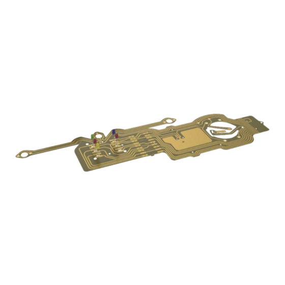
- Page 1 Installation Guide DASHBOARD FLEXIBLE PCB Volkswagen Transporter / Caravelle / Joker… T3/T25 until July 1984 (« vertical » connector) Petrol and Diesel Models with or without clock option...
- Page 2 Version du 05/03/2021 ind C...
-
Page 3: Table Of Contents
Table of Contents Disassemble the old PCB ................4 Disassemble the 14 pin multipoint connector ..............4 Dismantle the clock connection (for vehicles with this option) ..........4 Dismantle the fuel and engine temperature gauges (for vehicles with this function) .. -
Page 4: I) Disassemble The Old Pcb
Disassemble the old PCB Disassemble the 14 pin multipoint connector Carefully remove the piece of plastic surrounding the 14 pin connector (there is a clip on either side of the piece). Dismantle the clock connection (for vehicles with this option) Remove the cover of the +12V connector found on the back of the clock unit. -
Page 5: Dismantle The Fuel And Engine Temperature Gauges (For Vehicles With This Function)
Unscrew the screws of the -12V terminal on the back of the clock unit using a cross-head (Philips) screwdriver. Dismantle the fuel and engine temperature gauges (for vehicles with this function) Unscrew the 3 nuts connecting the temperature gauge to the PCB using a 7mm wrench. -
Page 6: Disconnect The Earth On The Voltage Regulator
Unscrew the 2 nuts connecting the fuel gauge to the PCB using a 7mm wrench. Disconnect the earth on the voltage regulator Unscrew the screw in the centre of the voltage regulator using a crosshead (Philips) screwdriver. Version du 05/03/2021 ind C... -
Page 7: Dismantle The Indicator Light Bracket
Dismantle the indicator light bracket Unscrew the 2 screws at either end of the bracket. Dismantle the dashboard light bulbs Turn the 3 light bulb holders a quarter of a turn each to release them from the speedometer unit. Version du 05/03/2021 ind C... -
Page 8: Remove The Pcb From The Speedometer Unit
Remove the PCB from the speedometer unit Be careful not to break the small holding studs of the PCB on the dashboard Remove the indicator light unit from the dashboard Be careful not to break the clips below the light indicator unit Unscrew the screw located above the indicator light unit (1), then rotate (2) the light indicator unit to remove the two clips located below. -
Page 9: Reassemble The New Flexible Pcb
Reassemble the new flexible PCB If your vehicle does not have the clock option, cut the two tabs located in the hole of the fuel gauge side (see Photo) to avoid a short-circuit! Install the new Flex PCB onto the dashboard Mount the indicator light bracket (recovered from the old PCB) onto the new Flex PCB (notch facing upwards). -
Page 10: Reassemble The Indicator Light Unit
Reassemble the indicator light unit checking that the LEDs Mount the indicator light unit onto the PCB are in front of the intended indicator compartments Screw the two screws to reassemble the bracket onto the indicator light unit. Version du 05/03/2021 ind C... - Page 11 Mount the PCB with the indicator light unit on the dashboard starting with the indicator light area, ensuring that the LEDs are in front of their intended corresponding compartments. Screw in the screw at the top of the indicator lights unit. Version du 05/03/2021 ind C...
-
Page 12: Position The Pcb On The Dashboard
Position the PCB on the dashboard Position the PCB on the holding pads, fasten the fuel and temperature gauge connectors by pressing gently around the holes. Connect the earth of the voltage regulator Screw in the screw located in the centre of the voltage regulator. Version du 05/03/2021 ind C... -
Page 13: Reassemble The Fuel And Engine Temperature Gauges (For Vehicles With This Function)
Reassemble the fuel and engine temperature gauges (for vehicles with this function) Tighten the 2 nuts connecting the fuel gauge to the flex PCB (be careful not to damage the indicators by tightening too tight) using a 7mm wrench. Tighten the 3 nuts connecting the temperature gauge to the flex PCB (be careful not to damage the indicators by tightening too tight) using a 7mm wrench Version du 05/03/2021 ind C... -
Page 14: Reassemble The Clock Connection (For Vehicles With This Option)
Reassemble the clock connection (for vehicles with this option) Pass the -12V tab under the connector of the earth of the clock and screw it onto the terminal. Pass the connector through the hole in the +12V tab, then fold the tab over the connector, reassemble the cover of the +12V connector. -
Page 15: Reassemble The 14 Pin Multipoint Connector
Reassemble the 14 pin multipoint connector Fold the PCB around the edge of the 14 pin connector (make sure that the small pins are in the intended holes). Reassemble the 14 pin multipoint connector, taking care that it is mounted in the correct direction. Version du 05/03/2021 ind C... -
Page 16: Reassemble The Dashboard Lights
Reassemble the dashboard lights Position the PCB on the lighting bracket and turn each of the 3 lightbulb supports a quarter of a turn to reconnect them to the speedometer unit. When reassembling, make sure the 14 pin connector is in good condition and that none of the pins are defective, otherwise this could damage the product.
Need help?
Do you have a question about the 251919059J and is the answer not in the manual?
Questions and answers