Table of Contents
Advertisement
Quick Links
For Model numbers:
WARNING: If the information in this manual is
not followed exactly, a fire or explosion may
result causing property damage, personal injury
or loss of life.
WHAT TO DO IF YOU SMELL GAS:
efficiency wall boiler
C99, C100, C140, C200
H100, H140, H200
Installation
Service and maintenance
Start up
Parts
Switch off the appliance.
Shut off the gas supply.
Open the windows.
Do not try to light any appliance.
Do not touch any electric switch.
Do not use any phone in your building.
Leave the house.
Immediately call your gas supplier from a
neighbour's phone. Follow the gas
supplier's instructions.
If you cannot reach your gas supplier,
call the fire department.
WHAT TO DO IF YOU SMELL FLUE
GASSES:
Switch off the appliance.
Open the windows.
Shut off the gas supply.
Leave the house.
Contact a registered installer or
a registered service center.
Eco-King high
Installation Manual
2019
Advertisement
Table of Contents
Troubleshooting

Related Manuals for Eco-King C99

Summary of Contents for Eco-King C99
- Page 1 Eco-King high efficiency wall boiler Installation Manual 2019 For Model numbers: C99, C100, C140, C200 H100, H140, H200 Installation Service and maintenance Start up Parts WARNING: If the information in this manual is not followed exactly, a fire or explosion may result causing property damage, personal injury or loss of life.
-
Page 2: Table Of Contents
Table of contents Part 1 – Introduction Hazard definitions User responsibilities Boiler operation Manufacturer conditions Installer responsibilities When servicing boiler When pressure testing boiler Main parts Functionality of main parts Part 2 – Specifications / Technical data Part 3 - Appliance location Location checks Appliance Area Ventilation Air Openings Closet Installations... - Page 3 Table of contents (continued) Part 10 - Lighting the appliance / First start-up Fill and refill of the CH section General use of the control panel Setting of user parameters Weather dependent control Set the comfort level Set the maximum central heating temperature Set the hot water comfort Vent Diagnosis menu...
-
Page 4: Part 1 - Introduction
Part 1 – Introduction Hazard definitions The following defined terms are used throughout this manual to bring attention to the presence of hazards of various risk levels or to important information concerning the life of the product. Indicates presence of hazards that can cause severe Warning personal injury, death or substantial property damage. -
Page 5: For Your Safety, Read Before Operating
Part 1 – Introduction FOR YOUR SAFETY, READ BEFORE OPERATING WARNING: If you do not follow these instructions exactly, a fire or explosion may result causing property damage, personal injury or loss of life. A. This appliance does not have a pilot. It is If you cannot reach your gas supplier, call equipped with an ignition device which the fire department. - Page 6 Compliance of this boiler with CSA B51 has not been verified due to an exemption provided in a provincial pressure vessel code. The installation of the Eco-King gas appliance must conform to the requirements of this manual, your local authority and the CAN/CGA B149 Installation Codes. Where required by the Authority, the installation must conform to the standard for Controls and Safety Devices for Automatically Fired Boilers ANSI/ASME CSD-1.
-
Page 7: User Responsibilities
The Installer assumes all responsibility for a safe installation and that it meets the requirements of the Eco-King instruction manual, as well as National and local codes. It is also the installer’s responsibility to inform the User / Owner of their obligation with respect to the description under “User Responsibilities”. - Page 8 Part 1 – Introduction The Eco-King is a high efficiency gas wall boiler and is designed for heating a central heating (CH) system and producing domestic hot water (DHW). The main functions of the Eco-King boiler are: 1.) Heating the house: Central Heating (CH) 2.) Producing Domestic Hot Water (DHW)
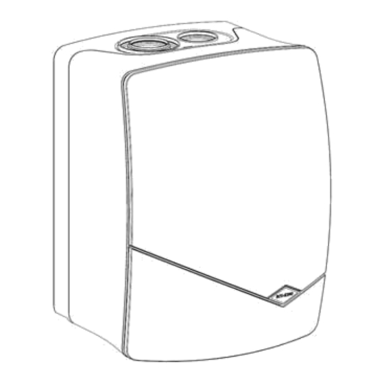
- Page 9 Part 1 – Introduction Boiler dimensions All dimensions mentioned in the figures below are in inches.
-
Page 10: Main Parts
Part 1 – Introduction Main parts A: Fan B: ignition / ionisation electrode C: Flue gas temperature limiter (NTC) D: Maximum temperature fuse (TF) E: Manual vent F: Burner and heat exchanger G: Pump vent H: CH Supply sensor I: Magnetite filter J: Hydroblock K: Connections L: Internal expansion tank... -
Page 11: Functionality Of Main Parts
While a flow limiter takes care of the maximum hot water quantity, the tap water is heated up to about 61 °C (142 °F). The Eco-King boiler starts preparing tap water at a flow of 2.5 l / min (0.66 gal. -
Page 12: Part 2 - Specifications / Technical Data
Input (0-2000ft) Gross calorific BTU/h 16.000-105.000 19.800-135.000 26.900-185.000 value Eco-King C140 Eco-King C200 and CH operation Eco-King C99 / C100 and H100 and H140 H200 Nominal input (0-2000 ft) Gross Btu/h 16.000-89.000 / 16.000-90.800 19.800-113.600 26.900-159.000 calorific value Max Output (0-2000 ft) at 50/30 Btu/h 85.000... - Page 13 High Altitude Operation The Eco-King boiler is designed to operate at its maximum listed capacity in installations less than or equal to 610 m (2000 ft) above Sea Level. Since the density of air decreases as elevation increases, maximum specified capacity should be de-rated for elevations above 610 m (2000 ft) in accordance with the table underneath.
-
Page 14: Part 3 - Appliance Location
Location checks The wall must be strong enough to carry the weight of the Eco-King boiler. The boiler shall be installed such that the gas ignition system components are protected from water (dripping, spraying, rain, etc.) during boiler operation and service (circulator replacement, condensate trap, control replacement, etc.). -
Page 15: Closet Installations
Part 3 - Appliance location Closet Installations For closet installations, it is necessary to provide two ventilation air openings as shown in Figure 3-1 each providing a minimum area equal to 22 cm per kW (1 in per 1000 Btu/hr), but not less then 645 cm (100 in and within 152 mm (6”) of the top and bottom of the closet door. -
Page 16: Prior To Wall Mounting
Part 3 - Appliance location Prior to wall mounting Care must be taken to place the boiler in a safe location prior to installation on the wall to prevent damage to the mechanical connections. The delivery contains: The boiler; Installation manual for the installer; User manual for the homeowner; A wall support bracket;... -
Page 17: Part 4 - General Venting
Installations must comply with CSA B149.1 and local requirements. Warning The Eco-King boiler cannot share a common vent or air-intake with multiple appliances. Failure to comply will result in serious injury or death. -
Page 18: Venting Options
Part 4 - General venting Warning Do not store or use gasoline or other flammable vapors and liquids in the vicinity of this or any other appliance. Failure to follow instructions may result in serious injury or death. Warning Only use vent and air systems as specified in this manual. Notice Venting Options - Due to potential moisture loading (build-up) along the exterior wall, sidewall venting may not be the preferred venting option. -
Page 19: Concentric Installation
Part 4 - General venting Concentric installation These instructions must be followed together with the instructions in the manual that is supplied with the roof or wall terminal. That manual gives special instructions for applications, pressure drops, maintenance and mounting of the complete vent system. -
Page 20: Cut-Able Installation
Part 4 - General venting Figure 4.3 Bracket securing Warning Use only the provided self tapping screws, these screws have the correct length. Using screws with a longer length will damage the actual PP vent. Cut-able installation These instructions must be followed together with the instructions in the manual that is supplied with the roof or wall terminal. - Page 21 Part 4 - General venting 3. Check that the seal is retained correctly in the groove. 4. Take precautions with horizontal installation, the slope must be 5 cm per meter (0.60 inch/feet) towards the boiler. 5. Fix a bracket on a fixed part of building (i.e. wall) if necessary. 6.
-
Page 22: Installation Of A Vent System Configuration With Wall Terminal
Normal operation of the Eco-King appliance does not result in deposits of combustible soot in venting systems. However, a poorly adjusted or malfunctioning appliance can deposit soot and other debris which can enter the vent system. -
Page 23: Additional Instructions For Termination Through A Wall With A Wall Terminal
Part 4 - General venting Additional instructions for termination through a wall with a wall terminal. The concentric wall terminals can be installed through a wall made of combustible material, no extra parts are necessary. The venting system shall terminate in accordance with the requirements of CAN/CGA-B149., Natural Gas Installation Code. - Page 24 Part 4 - General venting Figure 4.10 Flue terminal hole cutting 4. Determine the wall thickness and, if necessary, cut the wall terminal to the desired length. Remove all burrs from the cut terminal. NOTE: The length of the flue terminal is correct if outer wall plate, or rosette, is flush with the outside wall.
-
Page 25: Installation Of A Vent System Configuration With Roof Terminal
Normal operation of the Eco-King appliance does not result in deposits of combustible soot in venting systems. However, a poorly adjusted or malfunctioning appliance can deposit soot and other debris which can enter the vent system. -
Page 26: Additional Instructions For Termination Through A Roof With A Roof Terminal
Warning The instructions of the appliance manufacturer with regard to the minimum trap height of condensate drain must be followed. If the height is not enough the flue gases can be blown out under a locked vent condition before the appliance’s blocked vent detection system can function. Additional instructions for termination through a roof with a roof terminal: The vent system must terminate at least 2 feet above the roof line or any wall or vertical structure within 10 feet. - Page 27 Figure 4.18 Location 5. Place the weather collar into position. See figure 4.19. 6. Carefully insert the flue terminal through the weather collar from outside the roof. Notice Do not turn cap. See figure 4.19. 7. Assure that the flue terminal is plumb using a level or similar device. See figure 4.19. 8.
-
Page 28: Mandatory Pre-Commissioning Procedure For Plastic Venting
Part 4 - General venting Warning The concentric vent pipe should extend fully into the appliance flue outlet adapter / air intake adapter. Make sure the concentric vent pipe extends in the appliance on the adapter location as shown in the figure underneath. Ensure that the venting system does not apply a load or strain on the appliance flue outlet adapter. -
Page 29: Venting Rules And Guidelines
Combustion air containing chemicals such as chloride, fluoride, bromine or iodine or dust and debris will cause corrosion damage of the heat exchanger voiding your Eco-King warranty. Refer to table 4.1 for a list of corrosive products and contaminants sources to avoid. -
Page 30: Part 5 - Vent /Air - Intake Termination Clearances
The quick reference table below is to be read in conjunction with the numbered notes as indicated and the Venting Rules and Guidelines in Section 4. The instructions detailed in this section are a combination of Eco-King specific and National Gas Code restrictions. - Page 31 Warning Do not install the Eco-King boiler into a common venting system with any other appliances. Failure to comply with this warning can cause flue gas spillage and leech carbon monoxide emissions into the surrounding air resulting in serious injury or death.
- Page 32 UL Listed ULC-S636 Venting PART 3 The use of single pipe Eco-King (M&G) polypropylene or any polypropylene venting rated to ULC S-636 is now available to be used with Eco-King Boilers. No special adapter needed. Please review the following instructions:...
- Page 33 Max Vent length runs with Eco-King PP single pipe Eco-King recommends using 3” polypropylene venting, however 2” venting is permitted. Single pipe straight, 45 or 90 terminations are permitted as well. In Table 1.2 the Eco-King Boiler vent lengths are outlined.
- Page 34 Venting Part 4 If all contaminants listed in Table 2.1 in the installation manual are STRICTLY AVOIDED, combustion room can be used as a source of air intake. This table is shown again below. Note: In new home installs it is mandatory to bring air in from outside the home while the home is being built. This is in done to prevent dust and any other contaminants from entering the boiler housing and affecting operation.
- Page 35 Venting Part 6: Vent Terminations for All Single Pipe Applications Intake and exhaust pipes should terminate at a rooftop or side wall location. Keep exhaust plumes well away from all building air intakes including those of neighbouring properties. All venting must be installed in accordance with the requirements of the jurisdiction having authority: in Canada, Part 8, Venting Systems of the B149.1-10 Code and any other local building codes are to be followed.
- Page 36 Unbalanced Terminations Eco-King also permits unbalanced flue terminations where exhaust is terminated at the roof of building and intake is piped directly to the boiler from building side wall. Follow guidelines for each as noted above in roof and wall termination sections.
-
Page 37: Part 6 - Condensate Drain
Part 6 - Condensate Drain This appliance produces liquid condensate in the heat exchanger and venting system as a product of combustion. Provisions must be taken to ensure that condensate does not collect in the venting system; therefore, all exhaust piping must slope back to the appliance a minimum of 5 cm per mtr (0.60 inch / feet). -
Page 38: Cleaning
Part 6 - Condensate Drain Cleaning It is recommended to clean the condensate drain once a year by rinsing / washing it with tap water: 1.) Shut off power to the appliance. 2.) Disconnect the condensate hose by turning the connection screw. 3.) Dismount the drain from the boiler by a turning movement (to the left). -
Page 39: Frost Protection
Part 7 - Central heating (CH) and Domestic Hot Water (DHW) circuit Warning If no diffusion-tight pipes for supply and return (CH circuit) are applied for radiators or floor heating, place a partition between the CH water of the boiler and the water in the system. E.g. use a plate heat exchanger. A plate heat exchanger prevents contamination of the heat exchanger by, among others, magnetite. -
Page 40: Control Module
(See figure 7.6 as well) Control module The Eco-King Boiler control module uses temperature sensors to provide both high limit protection and modulating temperature control. The control module also provides low water protection by sensing the water pressure of the CH system. Some codes / jurisdictions or insurance companies may require additional external controls for high limit and / or low water cutoff protection. -
Page 41: Connect The Supply And Return Piping Of The Ch Circuit
The supply pipe for cold tap water (Fig. 7.4) is provided with a flow limiter depending on the type of Eco- King boiler (e.g. Eco-King C100: 8l/min. (2.1 gal/min) of 60 °C (140 °F)). Connect the supply and return pipe in accordance with the (local) regulations. - Page 42 CH supply DHW outlet Flow limiter Cold tap water inlet (Combi boilers) Figure 7.4 DHW connectors, flow limiter location...
-
Page 43: Connect An External Expansion Tank
Part 7 - Central heating (CH) and Domestic Hot Water (DHW) circuit Connect an external expansion tank The boiler comes standard with a 11 liter (2,9 US Gallon) internal expansion tank. In case the total size of the installation configuration requires this, an extra expansion tank needs to be selected with regard to the total installation size and static pressure. -
Page 44: Installation Examples
Mains water s upply for filling loop (Hxxx) ty pes Tank supply hot (Hxxx types) CH and Tank return (Hxxx types) A B C D 1) Boiler layout : Eco-King Heating only appliance Legend Combi Combi appliance Internal Expansion Tank... - Page 45 Part 7 - Central heating (CH) and Domestic Hot Water (DHW) circuit Legend For boiler details refer to layout no. 1. Tank Heating Only appliance Room Thermostat Tank sensor Temperature Pressure Relief Valve Heating circuit 3) System layout: Heating only appliance with connected tank and heating circuit Legend For boiler details refer to layout no.
- Page 46 Part 7 - Central heating (CH) and Domestic Hot Water (DHW) circuit Legend Tank For boiler details refer to layout no. 1. Heating Only appliance Tank sensor Temperature Pressure Relief Valve Low Loss Header Pump and LLH External control only required if Room Thermostat pressure loss in served...
- Page 47 Part 7 - Central heating (CH) and Domestic Hot Water (DHW) circuit Legend For boiler details refer to layout no. 2. Combi Combi appliance Pressure Relief Valve Domestic Hot Water Low Loss Header External control Room Thermostat Pump and LLH only required if pressure loss in served system is too high.
-
Page 48: Part 8 - Installing Gas Piping
The gas connection tube diameter is not indicative of the gas pipe that should be connected to it. For example the connection on boiler is ½”, but the larger Eco-King boilers at 187,000BTU require a larger gas pipe to be piped to the boiler. -
Page 49: Part 9 - Electrical Connections Opening The
Warning In case the line cord gets damaged it must be fully replaced with an official Eco-King line cord (See section 13 for part numbers). The line cord and wall socket must be at any time reachable with regard to service purposes. - Page 50 Part 9 - Electrical connections Figure 9.3 Print circuit board main connections To Pump To Fan Ground CONNECTORS Pow er for Green / Yellow supply ground cables cable (Supply, Fan, Pump) Pump + Fan connector Slide WHITE cable tree CONNECTOR on / of BURNER CONT.
-
Page 51: Part 10 - Lighting The Appliance / First Start-Up
Part 10 - Lighting the appliance / First start-up Warning Use of electrical connections to the boiler other than described might result in unpredictable behaviour, or malfunction of the boiler. DO NOT WIRE ANY VOLTAGE, ONLY DRY CONTACTS TO CONTROL BOARD. - Page 52 Part 10 - Lighting the appliance / First start-up FOR YOUR SAFETY, READ BEFORE OPERATING WARNING: If you do not follow these instructions exactly, a fire or explosion may result causing property damage, personal injury or loss of life. A. This appliance does not have a pilot. It is If you cannot reach your gas supplier, call equipped with an ignition device which the fire department.
-
Page 53: Fill And Refill Of The Ch Section
The display shows the system pressure. The Eco-King boiler is provided with a special filling system. By opening the filling valve the CH- system will be filled. -
Page 54: General Use Of The Control Panel
Part 10 - Lighting the appliance / First start-up Before first domestic use of the boiler, software parameters need to be set and the appliance needs to be calibrated via the control panel and display. General use of the control panel P1: esc: escape / cancel P2: ok (confirm) | reset P3: CH temperature down... - Page 55 • *FOR PROPANE usage. On C99, C100, C140, H100 and H140 units, the Eco-King does not require a gas pipe changed, only a setting change on 15 from 1 to 2. When using propane on a H200 or C200 the Gas pipe in the boiler MUST BE CHANGED.
-
Page 57: Weather Dependent Control
Part 10 - Lighting the appliance / First start-up Weather dependent control In weather dependent control operation with an outside sensor, the boiler CH set point depends on the outside temperature and a pre-set weather compensation setting. In case an outside sensor and an on/off thermostat have been installed, the next steps need to be performed to pre-set weather dependent control: Select 1 for parameter no. -
Page 58: Set The Comfort Level
Part 10 - Lighting the appliance / First start-up Set the comfort level Set the maximum central heating temperature 1. Press [P3] or [P4]. The maximum CH temperature is shown. The ‘radiator’ symbol is flashing. 2. To change the CH temperature: a. -
Page 59: Vent
Part 10 - Lighting the appliance / First start-up Vent Warning Be careful when venting. The water can be hot. Use a cloth to collect spilled water. Make sure that the system is properly vented. This will avoid noise and comfort problems. The CH pump has an automatic vent and does not need venting. -
Page 60: Diagnosis Menu
Part 10 - Lighting the appliance / First start-up Diagnosis menu Read out measured values 1. Simultaneously press [P3] and [P4] for 5 seconds. The first value is displayed. 2. Scroll with [P3] and [P4] through the values (left on the display). The values are shown right in the display. - Page 61 Part 10 - Lighting the appliance / First start-up Left Mean value of Extra information (on the right) Software version Heat exchanger mode: 0 rest 2 start fan 3 pre ventilation 4 ignition 5 CH operation 6 DHW operation 7 heat up tap exchanger 8 anti-swing waiting time Modulation level flame + % Flame + %...
-
Page 62: Calibration
Before the first start up of the appliance (before calibration) check the gas type setting is set correctly (parameter 15, page 49). The Eco-King boiler is gas-adaptive, which means that the combination ionisation electrode and the burner pneumatically and electronically control the CO2 percentage. During calibration, the start current and the correct settings for the CO2 percentage are determined. -
Page 63: Automatic Calibration
4. Check the CO2 percentage on the flue gas analyzer. The percentage must be 9.0% (+/– 0.3%) for natural gas. For LPG it must be set to 10.0% (+/-0.3%) a.) In case the CO2 value is not within tolerance, the value must be adjusted. By pressing [P3] or [P4] the flame impedance is shown. -
Page 64: Part 11 - Installation Check List
Part 11 - Installation check list Installation Locate the appliance in accordance with Section 3 of this manual. Install the Vent/Air-Intake piping in accordance with Sections 4 and 5 of this manual. Ensure all joints are secured properly. The concentric Vent and Air-Intake piping must terminate outdoors. Perform the ‘Mandatory Pre-commissioning Procedure for Plastic Venting’... -
Page 65: Part 12 - Annual Maintenance And Inspection
Part 12 - Annual maintenance and inspection Warning This appliance must be inspected: At the beginning of every heating season, and at least every 12 months, by a Qualified Technician. When the appliance generates a series of similar faults. Annual Inspection Checklist Ask the user if there are any problems with the CH appliance or any other remarks. -
Page 66: Crystalline Silica
Part 12 - Annual maintenance and inspection Warning Crystalline Silica - Read carefully the warnings and handling instructions pertaining to Refractory Ceramic Fibers before commencing any service work in the combustion chamber. Take all necessary precautions and use recommended personal protective equipment as required. Make sure any gas is cleared from the combustion chamber. -
Page 67: Refractory Ceramic Fibers (Rfc)
Part 12 - Annual maintenance and inspection Check whether relief valve and air vents are not weeping. Low water cut off is flushed (if applicable). Examine all venting for evidence of leaks. Ensure vent screens are cleaned and clear of debris. - Page 68 Part 12 - Annual maintenance and inspection For more information on Refractory Ceramic Fibers, the risks, recommended handling procedures and acceptable disposal practices contact the organization below: Canada (CCOHS): Telephone directory listing under Government Blue Pages Canada—Health and Safety—Canadian Centre for Occupational Health and Safety;...
-
Page 69: Part 13 - Parts List
Part 13 - Parts list Cable harness For a list of parts that corresponds to the item numbers, refer to Table 13.1. Exploded Category Part name Part Number view no. Heat exchanger Heat Exchanger HE ISO 3+1 106-1028 C/H100 Heat exchanger Heat Exchanger HE ISO 4+1 106-1029 C/H140,... -
Page 70: Automatic Air Vent
Pressure relief valve (Watts type 202-1246 106-1240 374A) Seal gasvalve connections O RING 3/4" UNITEC 300 202-0135 106-1101 Seal expansion vessel O RING 1/2" UNITEC300 202-0136 106-1102 connection Seal hydro connection O RING 3/4" NBR 202-0137 106-1103 adapters Table 13.1. Parts list Eco-King... -
Page 71: Part 14 - Troubleshooting
Part 14 - Troubleshooting Warning Observe the following precautions when servicing the appliance. Failure to comply with these may result in fire, property damage, serious injury or death. Servicing the Appliance Disconnect or shut off all energy sources to the appliance: 120VAC power, water and gas. Identify and mark wires before disconnecting or removing them. -
Page 72: Fault Codes
Part 14 - Troubleshooting Fault codes Locking faults that block system operation appear in the display with a fault code. A warning symbol is placed above each fault code. Besides, the led ‘SERVICE’ lights up. Reset fault In a number of occasions in which a fault has occurred, the user can reset the fault and restart the system. In those cases, the text ‘reset’... -
Page 73: Trouble Shooting List
Part 14 - Troubleshooting Code Description Cause / Solution Lock-out no ignition 9, 10, 11, 26, 27, 28, 29, 30, 32, 44, 47, 76,77 Lock-out ionization problem - parasitic flame 29, 31, 32 Lock-out high limit temperature protection 5, 6, 8, 16, 17, 18, 19, 33, 34, 35, 39, 42, 43, 72, 73 Lock-out Primary temperature too high (>95 ºC) 5, 6, 8, 16, 17, 18, 19, 35, 39, 40, 42, 43, 72, 73 40min Lock - Insufficient temp. -
Page 74: Possible Causes And Solutions
Part 14 - Troubleshooting Code Possible cause Solution Supply and return switched at installation Check CH connections CH set point adjusted too low Check parameter 0 Max CH modulation set too low Check parameter 1 Max modulation time too long Check parameter 2 Pump speed too low Check speed in diagnose menu (24) and check parameter 4 and 5... -
Page 75: Part 15 Start Up Checklist
Part 15 Start Up Checklist Light Up Activities Date Completed 1)Verify piping Verify all piping and gas connections are completed secure and tight 2) Pressurize Use manual fill valve (white knob at bottom completed boiler and system left of boiler) by turning it open (clockwise turn) or if relying on PRV to pressurize system, open it until boiler pressure reaches 1.5 bar... -
Page 76: Part 16 Maintenance Checklist
PART 16 Maintenance Checklist WARNING Allowing the heater to operate with a dirty combustion chamber will hurt operation. Failure to clean the heat exchanger as needed by the installation location could result in heater failure, property damage, personal injury, or death. Such product failures ARE NOT covered under warranty Periodic maintenance should be performed once a year by a qualified service technician to assure that all the equipment is operating safely and efficiently. - Page 77 Supplier and Manufacturer: Eco-King Heating Products Inc. Unit 103, 2567-192nd Street Surrey, BC Canada V3Z 3X1 202-1262.3 | ID 2019...
Need help?
Do you have a question about the C99 and is the answer not in the manual?
Questions and answers