
Summary of Contents for Topex 7200
- Page 1 Control unit topex 7200 / 7250 Printer-, dispenser- and handling device Controller USER MANUAL Version 2.3 Keep for further use topex GmbH • Daimlerstraße 2 • D-73268 Erkenbrechtsweiler • www.topex.de...
-
Page 2: Address Of Manufacturer
Safety Devices Address of manufacturer topex GmbH Daimlerstraße 2 D-73268 Erkenbrechtsweiler Phone: (+49) 7026 / 9316 - 0 Internet: www.topex.de Email: zentrale@topex.de Service und Support Anschrift wie oben Tel. (+49) 7026 / 9316 - 80, oder (+49) 7026 / 9316 - 0... - Page 3 Types Control unit topex 7200 / 7250 Standard-control unit • topex 7200 • for labelling machine topex 7000 and topex 1000 used as printer • topex 7250 • for labelling machine topex 7000 and topex 1000 used as dispenser Options: •...
-
Page 4: Operating Personnel
Safety Devices Operating personnel Only personnel authorized by topex GmbH are allowed to operate the topex labelling machine. Additional requirements, qualifications and skills that are required for special works can be found in the respective chapter. -
Page 5: Table Of Contents
Use according to requirements ................16 Marking of labelling machine ................16 Workplace ......................16 Design and function ................... 17 2.4.1 Overview control unit topex 7200 / 7250 ............17 2.4.2 Optionen ......................20 2.4.3 Optional PC programs ..................21 Overview of interfaces .................. - Page 6 Safety Devices 3.1.4 Display area ....................... 36 Display area „SPS/PLC“ (optional, if PLC function applicable) ......37 3.1.4.1 Display area “Label” ................... 37 3.1.4.2 Display area „Setting“ ..................38 3.1.4.3 Display area „Setting“ (option) ................39 3.1.4.4 3.1.5 Control unit (printer) ................... 41 3.1.6 PLC-control (optional, if PLC function applicable)) ..........
- Page 7 Setup – PLC (optional, if the PLC function is applicable) ........54 3.2.7 3.2.7.1 Autostart......................54 3.2.7.2 Pressure time in ms ................... 54 3.2.7.3 Waiting time 1 in ms ................... 54 3.2.7.4 Waiting time 2 in ms ................... 54 3.2.7.5 Delay Aux.
- Page 8 Safety Devices PLC menu „Service“ ................... 69 3.5.2 3.5.2.1 Home position ....................69 3.5.2.2 Automatic cycle ....................69 3.5.2.3 Scan ........................70 PLC menu „Customer“ ..................70 3.5.3 PLC menu „Actuators“ ..................71 3.5.4 Submenu „SPS/PLC 1“ and „SPS/PLC 2“ ............71 3.5.4.1 Submenu „Stepper 1“...
- Page 9 Shutting down ....................88 Safety notes ....................... 88 Temporary shutdown..................88 Final shutdown / disposal ................... 89 Data processing with TopTerm ............... 90 Setting of IP-address and port with TopTerm ............. 91 File Download ....................93 File Upload ......................94 DiskUpload / DiskDownload ................
-
Page 10: Safety Devices
Safety Devices Safety Devices Explanation of symbols and reference notes Danger! This reference note means an immediate threatening danger for life and health of persons. Failure to observe these notes will result in severe damages to your health or even to your life. Warning! This reference note means a possible threatening danger for life and health of persons. -
Page 11: Dangers At The Controller Unit
Safety Devices Dangers at the controller unit 1.2.1 Sources of danger There can be a dangerous electrical voltage on the supply cable of the labelling machine: • On the supply cable between control unit and labelling machine • On the electrical connectors of driving motor, on the printer and inside the housing of the labelling machine. -
Page 12: Safety Instructions
Warning! Exclusively authorized stuff, trained by topex GmbH and with the required qualifi- cations, may operate and adjust the control unit topex 7200 / 7250. Improperly made changes on the control unit might result in faults or damages to the labelling system and in injuries for the operator. -
Page 13: Responsibility Of Stuff
Safety Devices 1.3.2 Responsibility of stuff All persons that work on the machine are, before start of work, obliged to: • follow the basic regulations of job safety and the rules of accident prevention, • read the safety chapters and warnings of this user manual. 1.3.3 Safety measures in normal operation The machine shall only be operated by trained and authorised personnel who are... -
Page 14: Safety Measures For Maintenance And Servicing
Safety measures for maintenance and servicing Information! We recommend that maintenance or repairs are carried out in principle by specially trained personnel only or to assign topex service technicians for this purpose. Carry out the setup-, maintenance- and inspection works on the due date. -
Page 15: Risks By Electrical Power
1.3.5 Risks by electrical power Repair work on the electrical equipment of the machine shall only be carried out by qualified electrical personnel or by topex personnel. • Check the electrical equipment on a regular basis. • Refasten loose connections. -
Page 16: Product Description
Product description Product description Use according to requirements The control unit topex 7200 / 7250 is used to control the labelling machine topex 7000 and topex 1000. The system is designed for the integration in existing industrial systems. The ma- chine must not be operated in potentially explosive atmosphere... -
Page 17: Design And Function
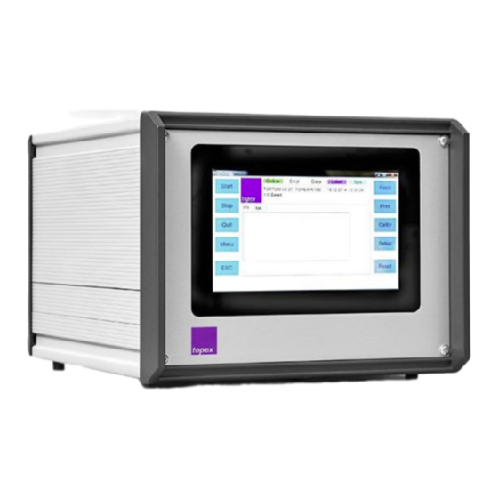
Touch panel The controller topex 7200 / 7250 consists of the control unit and the correspond- ing firmware. It serves to position the stepping motor and to control the printhead as well as the input and output signals and the handling devices. - Page 18 Product description 15 14 Figure 3 Control unit topex 7200 / 7250 – rear view Item Description Item Description Power supply PLC board I (optional) Main switch 0/I Date line machine, PrnCtrl 24-V-power supply for labelling Mouse via PS2 interface...
- Page 19 I/O interface motor rier head (1000-simulation) Peripheral Data ba- Monitor ckup Keyboard Power 24V Print Ctrl Control unit Mouse topex 7200 / 7250 Power COM1 COM2 LAN1 LAN2 Customer Inputs Outputs Handling Scanner / Service-PC 230V Sensors camera IP = 192.168.1.230...
-
Page 20: Optionen
EN 60950-1. Information! More detailed information concerning the control commands and printer functions can be found in the Programming Manual – control unit topex 7200 / 7250. 2.4.2 Optionen • Up to 3 PLC boards to control a handling device, •... -
Page 21: Optional Pc Programs
I/O card for a PLC on the control unit is required. For details refer to chapter 10. toplabel: Graphical user interface to design label layouts for printing. Figure 5 Design of label layouts with toplabel. Example Further details for the optional PC programs can be provided by the sales depart- ment of topex. -
Page 22: Overview Of Interfaces
The data interface can be executed wither as TCP/IP interface or as a serial RS232 interface. Information! For more detailed information concerning the data telegrams refer to the Programming manual – control unit topex 7200 / 7250. Feedback: • Load label (<ESC>y6;..;<CR>): - „+“ if file has been loaded successfully, - „-“... -
Page 23: Tcp/Ip Data Interface Lan1
Product description 2.5.2.1 TCP/IP Data interface LAN1 If the data communication is selected via TCP/IP this is realized via the LAN1- interface, i.e., here the data host of customer is connected (PLC or PC) via the LAN1- interface. • IP-address: Default value DHCP (adjustable via „Setup Interface“), •... -
Page 24: Serial Peripheral Interface Com2
Product description Pin Signal Sender Function Computer Receiving data. Receives data transmitted by the computer. Printer Transmit data. Available if XON/XOFF-protocol was selected. Additionally, the status can be re- quested via this data cable. Hardware-Handshake Signal grounding Hardware-Handshake Hardware-Handshake Hardware-Handshake •... -
Page 25: Power Supply
Product description Pin Signal Sender Function Computer Receiving data. Receives data transmitted by the computer. Printer Transmit data. Available if XON/XOFF-protocol was selected. Additionally, the status can be re- quested via this data cable. HIGH → Printer is ready Printer LOW →... - Page 26 Label is applied onto the product. Step se- quence must contain the object „E_Apply- ing?“ (TopTerm RemoteControl) External acknowledging Error can be acknowledged at topex panel or externally. Emergency stop IO Emergency stop cycle closed 24 V emergency stop from...
-
Page 27: Interfaces Of The Labelling Machine
Interfaces of the labelling machine For operation the labelling system is connected via a connecting cable to the con- trol unit topex 7200 / 7250. The control unit supplies also the electrical power for the stepping motor and the printhead (if applicable). - Page 28 Product description Figure 6 Connection cable and interfaces on the machine Item Description Item Description Connection power supply 24 V Power supply 24 V DC (POWER) Connection data line I/O-interface Data-interface (DATA) LEDs, die den Status von Schnittstellensignalen wiedergeben: Description Assignment LED ERROR, yellow to I/O-interface Pin 13...
-
Page 29: I/O-Interface (Junior-Simulation) On Printer / On Dispenser
Product description 2.5.6.1 I/O-interface (Junior-Simulation) on printer / on dispenser Description of female connector on interface board of labelling machine: Connector type: 15-ping SUB-D connector 2-row This interface is used for the IO-communication with the PLC of customer if the control unit is not equipped with a PLC-board. -
Page 30: Data Line Between Control Unit And Printer
Product description 2.5.6.2 Data line between control unit and printer Socket designation on control unit: PrnCntrl Socket designation on interface board on the labelling machine: DATA The controlling of printer is made via TTL- signals, which are provided by the I/O board that is mounted in the printer control unit. -
Page 31: Technical Data
Product description Technical Data General data Basic function Stepping motor- and printer control Handling Menu-driven Controlling unit 1/2 19“-housing, with ventilator, ex- Construction cess temperature protection and real time clock Controller 64 Bit CISC Quad-Core Microprocessor • 64GB SSD Flash-memory, Memory, •... - Page 32 Product description Character set • Arial and Courier, definitely Character set scaled • Arial freely scaled Font generator or toplabel (optional) all True Type Fonts • Inverse print Invertibility • Mirror print Barcodes EAN-8, EAN-13, EAN-128, Code 2 of 5 interleaved, Code 39, Code 128 A, B, C, Codablock F 2D-Codes...
-
Page 33: Touch Panel Operation
Touch panel operation Touch panel operation Information! The functionality of the control unit differs depending on the design of the label- ling system, e.g. with or without printhead unit, with or without PLC control. Labelling systems with print unit are hereinafter referred to as „printer“. ... -
Page 34: Touch Panel Operation (Printer)
Touch panel operation Touch panel operation (printer) 3.1.1 Main menu (printer) Figure 7 Main menu (printer),example Item Description Item Description Control unit labelling system, Display area depending on the see chapter 3.1.5 selection PLC control (optional, if PLC ap- Header with status display plicable), see chapter 3.1.6 Selection display area Info area under the header... -
Page 35: Header With Status Display
Label Lights purple when the data record is loaded or transmitted. SPS/PLC Lights turquoise when the PLC is active. TOPEX Name of the current parameter set 3.1.3 Info area under the header Figure 9 Info area under the header... -
Page 36: Display Area
Touch panel operation 3.1.4 Display area Info Sps Label Setting Figure 10 Display area „Info“, example Item Description Item Description Selection of display area Info / Display depending on the selec- SPS/PLC / Label / Setting tion by item 1 In the title line, the display area can be switched between: •... -
Page 37: Display Area „Sps/Plc" (Optional, If Plc Function Applicable)
Touch panel operation Display area „SPS/PLC“ (optional, if PLC function applicable) 3.1.4.1 Figure 11 Display area „SPS/PLC“ Display area “Label” 3.1.4.2 Figure 12 Display area „Label“... -
Page 38: Display Area „Setting
Touch panel operation Display area „Setting“ 3.1.4.3 Figure 13 Display area „Setting“ Item Description Item Description Input area for various parame- Control button for test print out- ters put. -
Page 39: Display Area „Setting" (Option)
Touch panel operation Display area „Setting“ (option) 3.1.4.4 Figure 14 Display area „Setting“ Item Description Item Description List of settings Edit the selected setting Move the selection bar up/ down Create a new setting When creating a new setting a window for entering the setting name appears, see Figure 15. - Page 40 Touch panel operation Figure 15 Enter setting name Figure 16 Edit and save settings...
-
Page 41: Control Unit (Printer)
Touch panel operation 3.1.5 Control unit (printer) Function Feed Feed of a blank label. Print Feed of a printed label. When no data record has been yet transmitted or selected a test label is printed. Otherwise the last printed data record is used (if „Delete after print“... -
Page 42: Setup-Menu (Printer)
Touch panel operation Setup-menu (printer) By pressing the Setup-key in the main menu you are entering the setup-menu. Stepper Figure 17 Setup-menu, level 1 Item Description Item Description Submenu, selected line is col- Arrow key right, activates the ored selected line, possibly with en- tering a password Stepper (optional): see chapter 3.2.10. - Page 43 Touch panel operation Figure 18 second level, example „Label“ Item Description Item Description Submenu, selected line is col- Arrow key right, activates the ored selected line, possibly with en- tering a password Arrow keys up, down, moves Close button, return to the next the cursor in the list higher level By pressing the arrow-keys up, down you move the cursor up and down in the...
-
Page 44: Third Level
Touch panel operation 3.2.1.2 Third level By pressing the arrow key right you move from the second to the third level. For entering values you get to the corresponding dialog to change the values. Figure 19 Dialog for numeric input of values, example „XOffset“ Item Description Item Description Current value... -
Page 45: Overview Setup-Menu (Printer)
Touch panel operation 3.2.2 Overview Setup-menu (printer) • Information chapter 3.2.3 • Label chapter 3.2.4 • Quality chapter 3.2.5 • Device chapter 3.2.6 • PLC (optional, if PLC ap- chapter 3.2.7 plicable) • Interface chapter 3.2.8 • System chapter 3.2.9 •... -
Page 46: Setup - Info
Touch panel operation Setup – Info 3.2.3 Figure 21 Setup-Info 3.2.3.1 Warnings In this menu you can set whether warnings (Attention: No ERROR!) should be • confirmed (ESC), • only be displayed or • ignored (no display). Parameter area: Parameterbereich 3.2.3.2 Logfile The recording area of the logfile can be selected and activated here... -
Page 47: Counter
Touch panel operation 3.2.3.6 Counter The counter displays the number of labels which have been printed since com- missioning of the system. Parameter area: no parameter values, only display. 3.2.3.7 Firmware (password protected) Here you move from the user interface to the firmware background service. 3.2.3.8 Echo By activating this function, a logging of the data communication is started. -
Page 48: Setup - Label
Touch panel operation Setup – Label 3.2.4 Figure 22 Setup-Label 3.2.4.1 XOffset Shifts label layout to be printed on dot line in X direction. The printout can be shifted independent of the transmitted label layout subse- quently to the left or right (global parameter). The parameter X-alignment (see chapter 3.2.4.5) defines where the zero point in X- direction is. -
Page 49: Label Length
Touch panel operation 3.2.4.4 Label length This value defines the label length in dots, only necessary when using continuous label material. If the value 0000 is set the label length is defined by the last calibration run. 12 Dots = 1 mm Parameter area: 0000/+9999 Dot 3.2.4.5 X-alignment... -
Page 50: Setup - Quality
Touch panel operation Setup – Quality 3.2.5 Figure 23 Setup-Quality 3.2.5.1 Print speed This item defines the speed in mm/s. Parameter area: +005 / +120 mm/s 3.2.5.2 Heating value The heating value defines the power of the printhead. Parameter area: +001/+200... -
Page 51: Setup - Device
Touch panel operation Setup – Device 3.2.6 Figure 24 Setup-Device 3.2.6.1 Print with Print key This item sets the print-start performance. • Entering „On“ starts the print only when the print data is complete and the print-key or the input print-start is activated. •... -
Page 52: Print Enable / Delete After Print
Touch panel operation 3.2.6.4 Print enable / Delete after print Parameter area each: ON/OFF See table below: Print Delete after Function enable print The number of labels, transmitted with the print data, is printed. Example: <ESC>#3<CR> has the effect that 3 label cycles can be run before new data has to be transferred. -
Page 53: Continuous Material
Touch panel operation 3.2.6.5 Continuous Material With the parameter value „On“ the light barrier is set inactive. Then the synchroni- zation is made via the defined label length as described in chapter 3.2.4.4. Parameter area: ON/OFF 3.2.6.6 Medium transparent (password protected) With the parameter value „On“... -
Page 54: Setup - Plc (Optional, If The Plc Function Is Applicable)
Touch panel operation Setup – PLC (optional, if the PLC function is applicable) 3.2.7 Figure 25 Menu „Setup“ - „SPS/PLC“, example In the menu "setup" all periods are adjusted with a measurement unit of 1 ms. The scanner configuration is done here, too. All adjustments can be set only, if there is a PLC program installed, written with the software TopTerm RemoteControl. -
Page 55: Delay Vacuum Dot
Touch panel operation 3.2.7.6 Delay Vacuum Dot Switch-on delay of the vacuum opposite the start of the label dispensing. Instead of a time value, the feed rate is set in Dot, after which the vacuum is to be switched on. 3.2.7.7 Timeout Vakuum in ms Monitoring time of the vacuum switch (value in milliseconds). -
Page 56: Repeat Reading Not Okay
Touch panel operation 3.2.7.14 Repeat Reading not okay Requirement for the effectiveness of this parameter is that in the automatic se- quence chain das the object „scan not okay →“ is available. This counter is used to set the number of repetitions of the sequence chain start- ing with this object. -
Page 57: Setup - Interface
Touch panel operation Setup – Interface 3.2.8 Figure 26 Setup-Interface 3.2.8.1 address (password protected) Figure 27 Menu LAN1 Definition of the interface parameters of LAN1. Here the TCP/IP adresses can be entered manually via the ?-fields. LAN2 is the service-interface for updating and downloading the firmware and PLC-programs. -
Page 58: Data-Port (Password Protected)
Touch panel operation 3.2.8.2 Data-Port (password protected) Figure 28 Menu Data-Port Here you can select the data interface and define the port and baud rates. Definition of the interface parameters of COM1. COM1 is the general data inter- face for receiving labels, layout files, logos and print sequences Parameter format: COMx: baud rate, parity, data bit, stop bit 3.2.8.3 Scanner-Port (password protected) -
Page 59: Overwriting Data (Password Protected)
Touch panel operation 3.2.8.5 Overwriting data (password protected) There are 3 functions: • Overwriting: - Existing data is overwritten. • Overwriting after timeout: - Data telegrams received at a time of less than 5 seconds buffers the firm- ware into the print spooler and prints them one after the other. - Is the time between the data telegrams longer than 5 seconds, then the ex- isting data is overwritten. -
Page 60: Setup - System
This function defines the data processing of the control unit. • Is the option „Topex“ selected, the topex-printer syntax is processed. • Is the option „Zebra“ activated, the Zebra-syntax is processed. Parameter area: Topex (Standard) / Zebra (optional) / CAB (optional) / Junior (Standard) / dispenser (Standard) 3.2.9.3 Printhead (password protected) Printheads of 4 different widths (54, 104, 108 und 160 mm) are used. -
Page 61: Distance Ls (Light Barrier)(Password Protected)
Distance LS (light barrier)(password protected) This function sets the distance between light barrier and printhead and is decisive for the label synchronization. The models topex7200 and topex 1000 („ECO“) have different distances due to their construction. Parameter area: ECO / T7000 3.2.9.5... -
Page 62: Restore (Password Protected)
Touch panel operation 3.2.9.10 Restore (password protected) The files backed up in the D:\BACKUP folder are copied back to the root directory D:\Printer. Figure 30 Menu Setup – Backup With the field "Change" you can select the storage location of the backup. Figure 31 Menu Setup - Backup Another way of backing up data is to copy the D:\Printer folder to a network drive or external storage medium via Windows Explorer. -
Page 63: Setup - Stepper (Optional)
Touch panel operation Setup – Stepper (optional) 3.2.10 The „Stepper“ menu (optional) appears when using an electrically operated axis. In this menu the movement position as well as the moving speed and the timeout for end position control of the PLC program can be defined. Description Function Position GS/HP... -
Page 64: Touch Panel Operation (Dispenser)
Touch panel operation Touch panel operation (dispenser) Information! See chapter 3.1, Touch panel operation (printer). There are no print functions at the dispenser. 3.3.1 Control unit labelling machine (dispenser) Function Feed Feed of blank label. Calibr A calibration run is started, whereby approximately 4 labels are fed and measured. -
Page 65: Setup Menu (Dispenser)
Touch panel operation Setup menu (dispenser) By pressing the Setup key in the main menu you get to the setup menu. Stepper Figure 32 Setup menu, level 1 (dispenser) Item Description Item Description Submenu, selected line is col- Arrow key right, activates the ored selected line, possibly with en- tering a password... -
Page 66: Further Menu Items In Setup-Menu (Dispenser)
Touch panel operation 3.4.1 Further menu items in Setup-menu (dispenser) Information! For all further menu items refer to chapter3.2, Setup-menu (printer). There are no print functions at the dispenser. -
Page 67: Plc Menu (Optional, If Plc Available)
Touch panel operation PLC menu (optional, if PLC available) Figure 33 Main menu (printer), example Item Description Item Description PLC control, see chapter 3.1.6 Menu-key, Activation of PLC menu The PLC menu (see Figure 35) is displayed in the main menu by pressing the menu-key. -
Page 68: Overview Plc Menu
Touch panel operation Figure 34 PLC menu 3.5.1 Overview PLC menu • Service chapter 3.5.2 • Customer chapter Feh- ler! Ver- • Actuators: PLC1 / PLC2 / Stepper 1 chapter 3.5.4 chapter 3.5.4.1 chapter 3.5.4.1 Chapter 3.5.4.2 Figure 35 PLC menu... -
Page 69: Plc Menu „Service
Touch panel operation PLC menu „Service“ 3.5.2 Figure 36 PLC menu „Service“ 3.5.2.1 Home position This item starts the sequence chain of the home position run. The sequence has to be programmed with TopTerm RemoteControl and stored in the control unit. 3.5.2.2 Automatic cycle Figure 37 PLC menu „Automatic cycle“... -
Page 70: Scan
Touch panel operation 3.5.2.3 Scan A control reading with the currently connected scanner (camera) is made. If the code is read its content is shown on the display otherwise the message „Timeout“ is displayed. PLC menu „Customer“ 3.5.3 Figure 38 PLC menu „Customer“ Here the 4 Inputs and Outputs of the customer interface can be tested. -
Page 71: Plc Menu „Actuators
Touch panel operation PLC menu „Actuators“ 3.5.4 Figure 39 PLC menu „Actuators“ - „PLC 1“ Selection of the submenu „SPS/PLC 1“, „SPS/PLC 2“ and „Stepper 1“ in the header. Caution! All outputs of cylinders are not interlocked in manual mode. In case of wrong han- dling, there is danger of physical injury and danger of damage or destruction by collision! ... -
Page 72: Submenu „Stepper 1
Touch panel operation Figure 40 PLC menu „Actuators“ - „SPS/PLC 2“ Submenu „Stepper 1“ 3.5.4.2 A stepping motor (optional) can be controlled in the submenu „Stepper 1“, see Figure 41. The reference point („ref“), the home position (GS/HP) and the working position (WP) that were pre-defined via the menu, can be approached. -
Page 73: Transport And Installation
Observe the notes on transport and installation in the user manual of the labelling machine. Transport • The transport is made by a forwarding agent from the topex plant to the cus- tomer. 4.1.1 Packaging The control unit as well as attachments, cables pneumatic elements are packed separately in a carton/box and secured to the pallet. -
Page 74: Installation
Transport and installation Installation 4.2.1 Ambient conditions on installation site See chapter 2.6, „Technical Data“ Temperature and humidity, Power supply and compressed air connection Mounting Space See general drawing in documenta- tion folder 4.2.2 Installation notes • Normally the labelling machine is delivered in a completely assembled condition. -
Page 75: Commissioning And Operation
• For further information about the operation of the control unit refer to chapter 1. • Detailed information about the control commands and printer function can be found in the programming manual – control unit topex 7200 / 7250. • Make sure that the maximum allowed supply voltage is not exceeded. -
Page 76: Installation Of The Optional Dongles
Commissioning and operation Installation of the optional Dongles For the conversion of foreign formats in the print sequences (Option Zebra ZPL, CAB) the corresponding dongle must be plugged into the control unit board in or- der to activate this option. Procedure: •... - Page 77 Commissioning and operation Figure 43 Slot for Dongle Item Description Item Description Slot for Dongle Hard disk...
-
Page 78: Switching On
Commissioning and operation Switching on 5.4.1 Checks before switching on • Ensure that all safety devices are correctly mounted. If not remount them. • Check if the setup of the machine is correct and corresponding with the appli- cation. • Expel unauthorized persons from the labelling machine. 5.4.2 Processing •... -
Page 79: Troubleshooting
Troubleshooting Troubleshooting Safety notes Caution! By resolving failures dangerous situations can occur. Follow the safety regulations in chapter 1. • Block the access wide-ranging for unauthorized persons to the working area of the machine. • Switch off the control unit voltage-free. •... -
Page 80: General Errors
RS232Pin 2+ 3. TCP/IP: • Check settings of data inter- face: IP-address and Port 9100 • TCP/IP-Ping test. Controlling faulty Correct positioning and control se- quences of PC software on the ba- sis of the Programming Manual topex 7200 / 7250... -
Page 81: Error Messages On System Level
Troubleshooting 6.2.2 Error messages on system level Error messages are shown as clear text on the touch panel. 6.2.2.1 Error messages and their consequences It is possible that various error messages occur at the same time, e.g. subse- quent errors. In this case the error with top priority is displayed. The priority in- creases with rising error code number. - Page 82 Troubleshooting Error Reason Correction Label does not exist/ A label that was not stored in Store the required label in printer the printer was loaded. WARNING • Store desired font in printer Font does not exist/ A font configured for a text field does not exist in printer •...
- Page 83 Troubleshooting Error Reason Correction Runtime error/ see Compiler error see Compiler error ERROR I/O Card Error/ The I/O card that realizes the Change I/O card. printer functions is defective ERROR (Connection „Print Ctrl“on con- trol unit). • Change transfer ribbon sensor Transfer ribbon/ The sensor of transfer ribbon sends no feedback.
-
Page 84: Error Messages In Plc Program
Troubleshooting 6.2.3 Error messages in PLC program Only valid if the PLC program is activated in the control unit. Error Reason Correction • Check compressed air (6 bar) Timeout Cyl. WP The respective cylinder has not reached its working position. Rea- •... - Page 85 Troubleshooting Error Reason Correction Timeout Spec. input The special input can be pro- Check the requirement that is grammed with Timeout i.e., if the controlled by the special input. object in the sequence is active, this input must lead the signal HIGH in an adjustable time.
-
Page 86: Maintenance And Servicing
Information! • Use only original spare parts that are indicated in the topex spare part list. • Do not use thinner, acids or bases even not in thin concentration as cleaning agents. -
Page 87: Requirements For The Performing Personnel
• Follow the requirements for performing personnel, see chapter 7.2. • Use solely original spare parts that are indicated in the topex spare parts list. • Regard the provided information in the documentation folder. • Remount after end of maintenance works disassembled protection devices... -
Page 88: Shutting Down
Shutting down Shutting down Safety notes • Regard the safety notes in chapter 1, „Safety Devices“. • Block the access wide-ranging for unauthorized persons to the working area of the machine. • At disposal pay attention to environmental safety, risks to health, disposal requirements and the local possibilities of disposal according to the regula- tions. -
Page 89: Final Shutdown / Disposal
Shutting down Final shutdown / disposal • Respectively wait until the system is in home position. • Switch off the control unit. • Secure the control unit against unintentional restart. Lock respectively the main switch of the superior system and remove the key. Dismantle the machine in the following assembly units: Electronic waste Dismantle in groups (transfor-... -
Page 90: Data Processing With Topterm
Data processing with TopTerm Data processing with TopTerm Warning! Exclusively authorized stuff, trained by topex GmbH and with the required quali- fications, may carry out the data processing with TopTerm. Improperly made changes on the control unit might result in faults or damages to the labelling system and in injuries for the operator. -
Page 91: Setting Of Ip-Address And Port With Topterm
Data processing with TopTerm Setting of IP-address and port with TopTerm The IP-address and the port of the LAN2 interface of the control unit must be configured to 192.168.1.230 Port 9101 in the TopTerm program. It might be necessary to choose again under „file“ the function „SR-Terminal“. Figure 44 „Setting port“... - Page 92 Data processing with TopTerm Figure 45 Setting of IP-address and port of LAN 2 Figure 46 Status request...
-
Page 93: File Download
Data processing with TopTerm File Download Any files can be transmitted from the hard disk of the service PC to the control unit: • Select under „Topex7000“ the menu item „File Download“. Figure 47 File Download • Select the file to be transmitted in „Datei senden/Send file“- dialogue •... -
Page 94: File Upload
Data processing with TopTerm File Upload Any files can be transmitted from the control unit to the hard disk of the service • Select the menu item „File Upload“ under „Topex7000“. Figure 49 File Upload • Select the file to be transmitted in the dialog box „Directory“. •... -
Page 95: Diskupload / Diskdownload
Data processing with TopTerm Figure 51 Dialog box „Save file as“ DiskUpload / DiskDownload This function saves all important files and directories of the control unit on the Service PC or transmits them to the control unit. -
Page 96: Diskupload
Data processing with TopTerm 9.4.1 DiskUpload • Select the menu item „Explorer“ under „Topex7000“ • Then select the menu item „DiskUpload“. Figure 52 Explorer • Select in the dialog box „Speichern unter/Save as“ the target directory. Figure 53 Dialog box „Speichern unter/Save as“ •... -
Page 97: Diskdownload
Data processing with TopTerm 9.4.2 DiskDownload • Select the menu item „Explorer“ under „Topex7000“, see Figure 52. • Then select the menu item „DiskDownload“. • Select in the dialog box „Quellverzeichnis/source directory“ the source directory. Figure 54 Selection of source directory •... -
Page 98: Explorer
Data processing with TopTerm Explorer With this tool all files in the control unit can be edited, copied, deleted, up- and downloaded. • Select the menu item „Explorer“ under „Topex7000“, see Figure 52. The Ex- plorer window opens. • Select file with left mouse click, see Figure 55. •... -
Page 99: Edit File
Data processing with TopTerm 9.5.1 Edit file Files can also be changed directly in the control unit: • Select the menu item „Explorer“ under „Topex7000“, see Figure 52. The Ex- plorer window opens. • Select file with left mouse click, see Figure 55. •... -
Page 100: Files Of The Control Unit
Data processing with TopTerm Files of the control unit The following describes the file structure of the control unit. 9.6.1 Systemdateien D:\Printer\PrnCtrl\PrnCtrlS.exe Firmware service D:\Printer\PrnCtrl\Top7200.ini Setup parameters D:\Printer\PrnCtrl\Top7200.mnu Configuration of main menu (printer) D:\Printer\PrnCtrl\Top72004.mnu Configuration of main menu (dispenser) D:\Printer\PrnCtrl\digea.ini Hardware information D:\Printer\PrnCtrl\Top7200.txt Messages... -
Page 101: Topterm Remotecontrol-Interpreter, Menu Configuration And Plc Sequence Program
Data processing with TopTerm 9.6.3 TopTerm RemoteControl-Interpreter, Menu configuration and PLC se- quence program D:\Printer\PrnCtrl\standard.prd Project file D:\Printer\PrnCtrl\standard.sbs Global functions D:\Printer\PrnCtrl\standard.cly Object macros D:\Printer\PrnCtrl\control.def Definition of inputs, outputs, flags and variables D:\Printer\PrnCtrl\standard.mnu Menu configuration of PLC menu D:\Printer\PrnCtrl\*.cfg PLC sequence program (de- signed by RemoteControl) -
Page 102: Plc Programming With Topterm Remotecontrol
PLC programming with TopTerm Remote- Control Warning! Exclusively authorized stuff, trained by topex GmbH and with the required quali- fications, may carry out the PLC programming with TopTerm RemoteControl. Improperly made changes on the control unit might result in faults or damages to the machine and in injuries for the operator. -
Page 103: Selection
PLC programming with TopTerm RemoteControl 10.2 Selection The programming tool TopTerm RemoteControl is started via „TopTerm“ by the menu item Topex7000 / RemoteControl. Figure 57 Starting TopTerm RemoteControl 10.3 Operation The user interface is divided in 6 sections: • Commands: List of all available control objects •... - Page 104 PLC programming with TopTerm RemoteControl For each section of the automatic and home position sequence chain are 4 but- tons and 1 input field with the following functions available: • Schritt einfügen (Insert step): Inserts the current marked control object from the command section in front of the marked object of each list.
- Page 105 PLC programming with TopTerm RemoteControl Figure 59 Operation of TopTerm RemoteControl – insert step Figure 60 Operation of TopTerm RemoteControl – select step...
-
Page 106: Description Of Control Objects
PLC programming with TopTerm RemoteControl 10.4 Description of control objects All available control objects are displayed in the command section of the user interface of TopTerm RemoteControl. Each object displays while a sequence chain is active a text in the 2nd. - Page 107 PLC programming with TopTerm RemoteControl Control object Display text Description Zylinder AS Cylinder [1-10] WP The respective valves of cylinder work posi- tion (WP) are set and the corresponding in- puts are checked. The number of the cylinders to be programmed is entered in the respective input field of the sequence chain.
- Page 108 PLC programming with TopTerm RemoteControl Control object Display text Description niO Vakuum → No display This object sets a jump label in front of the step as from there the sequence chain should be repeated after a vacuum- Timeout. The repetitions are configured with the pa- rameter „Wdhlg.
-
Page 109: Data Of Control Unit At Acceptance Test
Data of control unit at acceptance test Data of control unit at acceptance test You can find the software version in the acceptance test record. • Firmware version of control unit The following files must be stored to the folder\Elektro\t7000 on the CAD-Server: •... -
Page 110: Uefi-Parameter
UEFI-Parameter UEFI-Parameter For checking or modifying of UEFI-parameters of the control unit you need a PS2- or a USB-keyboard. To get to the UEFI (Unified Extensible Firmware Interface) you have to press the delete key, after you have started the control until with the power button, on the connected keyboard several times until you enter the UEFI menu.
Need help?
Do you have a question about the 7200 and is the answer not in the manual?
Questions and answers