Advertisement
Quick Links
Advertisement

Summary of Contents for MERGEWORKS Grid Baffle
- Page 1 Grid Baffle Mounting Instructions INS-EBG...
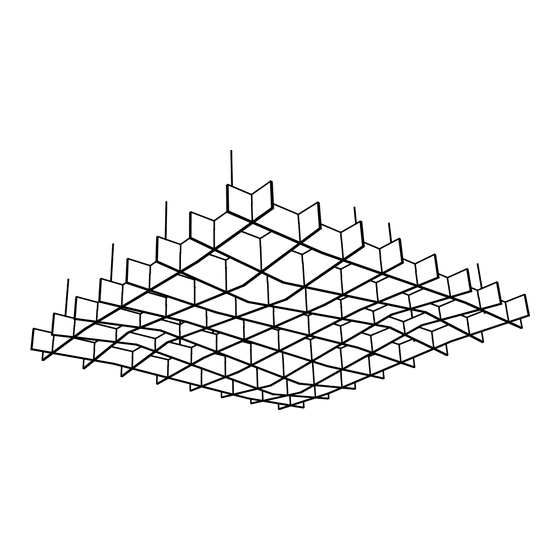
- Page 2 Grid Baffle Mounting Instructions Overview Grid baffles are fins that criss-cross each other on 12" spacing and hang from the ceiling. They come in three styles: REC, ANG, and WAV. REC are rectangular. ANG are sloped downward and upward with sharp points.
- Page 3 Illustration A Mount spacing and fin type pattern is as follows. 96" Width Fin Mounts 12" 24" 24" 24" 12" 6" 36" 12" 96" Depth 36" 6" Page 2...
- Page 4 B Fins B fins have downward slots that connect them with A fins. They also have upward slots which support D fins which run parallel to A fins. When hanging B fins, the first 2 are spaced parallel to each other at 36"...
- Page 5 Peaks and Valleys / Flipped Orientation It is imperative that the peaks and valleys of the interacting fins match up. To achieve this, some of the 8 foot fins will need to be flippped. Refer to previous views and illustrations to understand the flipped orientation.
- Page 6 Installation Hardware Part List - Steps 1-3 Description Item Fin Mount Cable Step 1 - Cut Cable (Item 2) to hang A fins. The cut length should be the desired depth from ceiling to top of panels plus approximately 6" for adjustment. If Loop Ceiling mount option is used add additional length to Cable length for your application.
- Page 7 Step 5 - Hang the A fins by inserting the loose cable end into the chosen Ceiling Mount. Depress the button on the bottom of the Ceiling Mount to feed the cable, and release to secure. Adjust for depth from ceiling and assure fins are level by adjusting the cable length at the fin mounts. Step 6 - Install B fins according to the illustrated spacing, by inter-locking the downward slots of the B fins with the upward slots in the A fins and sliding them down into place.
- Page 8 Step 7 - Install C fins by inter-locking the downward slots of the C fins with the upward slots in the A fins and sliding them down into place. C fins are perpendicular to A fins and are placed in pairs between the B fins. Step 8 - Install D fins by inter-locking the downward slots of the D fins with the upward slots in the B and C fins and sliding them down into place.
- Page 9 Staggering For Grid baffle installations larger than 8 feet in either direction, the fins must be staggered as shown in the following examples. Views are looking down from the top. A and D fin staggering: For Grid baffle installations of 16, 24, and 32 feet Shown is 16 feet.
- Page 10 Staggering B and C fin staggering: For Grid baffle installations of 16, 24, and 32 feet For Grid baffle installations of Shown is 16 feet. For each increment 12, 20, and 28 feet of 8 feet larger, there is an additional 8 foot fin inserted after the ones shown Shown is 12 feet.
- Page 11 Step 9 - After making any last adjustments for height and levelling, trim excess cable from Fin Mounts. Trim cable Page 10...
-
Page 12: Ceiling Mount Instructions
Step 2 - Connect cable attached to A fin into mount by depressing Depress to feed, button on the bottom of mount, feed approximately 1" of cable, release to secure. and release to secure. MergeWorks.com • 800-597-1195 info@MergeWorks.com Page 11...
Need help?
Do you have a question about the Grid Baffle and is the answer not in the manual?
Questions and answers