
Summary of Contents for Watson McDaniel ES Series
- Page 1 Made in the USA since 1878 Operating Instructions ES Series Electric Actuator PSF 402 2575700 Rev A Version 2016/06/28 Subject to changes!
- Page 2 2575700 Rev A...
-
Page 3: Table Of Contents
Spring retract / valve stem is extending Spring extend / valve stem is retracting Voltage supply Frequency Max. input power Force Stroking speed [mm/s] Watson McDaniel Model Code Configuration Chart ACTUATOR Code Actuator Code Power Supply Code Control Signal ESA Spring 115VAC 4-20mA ESB Spring... -
Page 4: Symbols And Safety
2575700 Rev A 1. Symbols and safety General dangers of non-compliance with safety regulations PSF actuators are built at state-of the art technology and are safe to operate. Despite of this, the actuators may be hazardous if operated by personnel that has not been sufficiently trained or minimum instructed, and if the actuators are handled improperly, or not used as per specification. -
Page 5: Usage As Per Specification
2575700 Rev A 2. Usage as per specification • PSF actuators are exclusively designed to be used as electric valve actuators. They are meant to be mounted on valves in order to run their motors. • Any other use is considered to be non-compliant and the manufacturer cannot be held liable for any damage resulting from it. -
Page 6: Function
2575700 Rev A Installation position Outdoor usage: When using the actuators in environments with high temperature fluctuations or high humidity, we recommend using a heating resistor. Figure 2: Installation positions 5. Function The PSF actuators are designed as electric valve actuators with failsafe function. The actuator is mounted onto the valve via pillars. -
Page 7: Valve Mounting
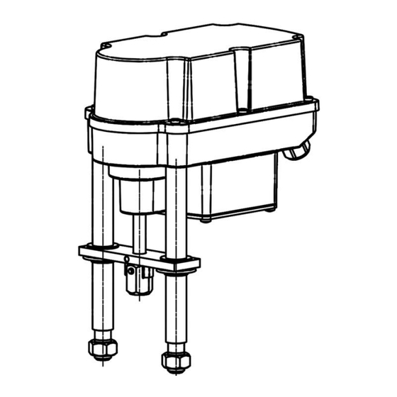
2575700 Rev A 7. Valve mounting pillar spring clamp with coupling pin coupling locking nut valve stem 1 mm bracket pillar nut Figure 4: Valve mounting 7.1 Valve mounting spring extend (SE) Initial position: Valve stem is retracted 1. Put actuator onto the bracket. 2. -
Page 8: Removing / Closing The Cover
2575700 Rev A 8. Removing / closing the cover Open the cover only in a dry environment. Open: Loosen the screws by using a screwdriver and unscrew them entirely out of the gear casing. The screws are protected against loss. Open the cover only in a dry environment. -
Page 9: Wiring Diagram
2575700 Rev A 9.2 Wiring diagram Figure 6 indicates the electrical connections for standard actuators. The wiring diagram inside the actuator is binding for the specific actuator wiring. For any optional accessories, see the separate wiring diagram in the corresponding installation instructions. -
Page 10: Operating Direction
2575700 Rev A 10.2 Operating direction SE = Spring Extend: Extend actuator stem / retract valve stem SR = Spring Retract: Retract actuator stem / extend valve stem Figure 7: Operating direction 10.3 Operator push button Function Action push button B1 push button B2 LED sequence >... -
Page 11: Status Display
2575700 Rev A 10.4 Status display Green LED Red LED Actuator not commissioned is flashing quickly Normal operation / actuator running Normal operation / actuator stationary Manual mode active is flashing alternately is flashing alternately Manual mode: Extend valve stem is flashing Manual mode: Retract valve stem is flashing... -
Page 12: Manual Operation
2575700 Rev A 10.7 Manual operation • Push button B1 and B2 simultaneously for minimum 3 seconds to change to manual operation mode. • Push button B1 to retract valve stem. • Push button B2 to extend valve stem. • Push button B1 and B2 simultaneously for minimum 3 seconds to exit from manual operation mode. 11. -
Page 13: Decommissioning And Disposal
2575700 Rev A 14. Decommissioning and disposal • Disconnect the mains supply and ensure that it is secured against an accidental switching-on. • Open the cover. • Remove external electrical connections. • Take off the actuator from the valve. Disposal For its disposal, the product should be treated as waste containing electrical and electronic equipment and should not be disposed of as household waste. -
Page 14: Declaration Of Incorporation Of Part Completed Machinery And Ec Declaration Of Conformity In Compliance With The Directives On Emc And Low Voltage
2575700 Rev A 15.2 Declaration of incorporation of part completed machinery and EC declaration of conformity in compliance with the directives on EMC and low voltage...
Need help?
Do you have a question about the ES Series and is the answer not in the manual?
Questions and answers