Table of Contents
Advertisement
Quick Links
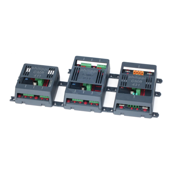
Relay module CMR 411, 811, 431 - CMR 412, 232
Operating and assembly instructions
Introduction / Use
The relay modules CMR 411, 811, 431 for single-pole fuse protection and CMR 412, 232 for
double-pole fuse protection are part of the PBUS system and are intended for operation on a
battery voltage DC 12V and 24V. Depending on the model, 2 to 8 functions / loads can be
switched with the CMR relay modules.
Each of the relays allows individual switching of loads and external devices by means of
events reported by other PBUS components. These are:
-
Switching of loads with dimmer control signal (max. 4 channels) for LED luminaires via
PWM control (suitable luminaires required)
-
Energy management, control of high-current relays
-
Control of an AC generator
-
Visualisation of alarm messages by means of external buzzer or indicator lights
-
Pump control for tank alarm
-
Thermoswitch: temperature-dependent control
-
Bilge monitoring
Each of the relays has a potential-free contact. Two PWM control outputs (dimmers) and a
control input are assigned to each relay.
The PWM control outputs are available as open-collector outputs (e.g. for Prebit LED
luminaires) and as voltage signals (level 5V).
V31 - APR 21
Relay module CMR x
and for CMR4 as of software version V30
Page
1
Advertisement
Table of Contents

Related Manuals for philippi CMR Series

Summary of Contents for philippi CMR Series
- Page 1 Relay module CMR 411, 811, 431 - CMR 412, 232 Operating and assembly instructions Relay module CMR x and for CMR4 as of software version V30 Introduction / Use The relay modules CMR 411, 811, 431 for single-pole fuse protection and CMR 412, 232 for double-pole fuse protection are part of the PBUS system and are intended for operation on a battery voltage DC 12V and 24V.
-
Page 2: Table Of Contents
Relay module CMR 411, 811, 431 - CMR 412, 232 Content 1 Safety instructions 1.1 Disclaimer ........................3 1.2 Warranty ........................3 1.3 CE mark .......................... 3 2 Scope of delivery 3 Technical data 4 Installation 4.1 Required equipment...................... 4 4.2 Installation location ....................... -
Page 3: Safety Instructions
Both compliance with the operating instructions and the conditions and methods during installation, operation, use and maintenance of the CMR cannot be monitored by philippi elektrische systeme. We therefore accept no responsibility or liability whatsoever for losses, damage or costs arising from incorrect installation and improper operation. -
Page 4: Installation
Relay module CMR 411, 811, 431 - CMR 412, 232 4 Installation 4.1 Required equipment The following parts are required to install the CMR: M12 network cable for connection to other P-BUS components. 4.2 Installation location Mount the relay module CMR in a protected, dry and accessible place so that the fuses/circuit breakers can be changed at any time. -
Page 5: Connection
Relay module CMR 411, 811, 431 - CMR 412, 232 4.4 Connection The power supply of the CMR is connected to the two (on CMR 811 and 431 double (top and bottom)) connection bolts (+) and (-). Ring cable lugs M5 or M6 (CMR 431, 232) must be used for this. - Page 6 Relay module CMR 411, 811, 431 - CMR 412, 232 Connection power supply 1-pole versions CMR 411, 811, 431: Power supply connection 2-pole versions CMR 412, 232: V31 - APR 21 Page...
-
Page 7: Configuration Of The Relay Channels
Relay module CMR 411, 811, 431 - CMR 412, 232 5 Configuration of the relay channels The individual functions of the relays of the relay module CMR are configured via the system monitors PSM and PSL. The menu item Settings/Devices/Relay module lists all relay modules CMR connected and logged on to the PBUS. -
Page 8: Digital Switching Of Consumers
Relay module CMR 411, 811, 431 - CMR 412, 232 5.1.1 Digital switching of consumers Each (relay) channel can be switched via two paths: Digitally via the monitor (P-bus) or directly on the relay module via a button ((IN), (plus- switching)). -
Page 9: Configuration On The Psm
Relay module CMR 411, 811, 431 - CMR 412, 232 5.1.3 Configuration at Monitor PSM On the PSM system monitor, the consumer relays are assigned to the screen buttons via the menu item Settings - Consumers. This must be done individually for each monitor as each monitor can be configured differently. -
Page 10: Energy Management Function
Relay module CMR 411, 811, 431 - CMR 412, 232 5.2 Energy management function This function is selected to control high-current relays to implement energy management or to switch loads directly. In this way, consumer groups are switched off to protect the battery from deep discharge. -
Page 11: Configuration Energy Management On-Pulse / Off-Pulse
Relay module CMR 411, 811, 431 - CMR 412, 232 5.2.1 Configuration Energy Management On/Off Energy management, control of monostable high-current relays with ON/OFF contact Battery setting: A battery connected to the PBUS with SHC Alarm setting: Alarm capacity, reserve and empty alarm are available for selection. -
Page 12: Configuration Generator On/Off
Relay module CMR 411, 811, 431 - CMR 412, 232 PLEASE NOTE: If the setting with pulse function is selected, the control signal and the LED are connected to the on-pulse relay! 5.3.1 Configuration Generator On/Off Control of an AC generator Setting start and stop time: Operating time of the generator. -
Page 13: Configuration Alarm Signal
Relay module CMR 411, 811, 431 - CMR 412, 232 5.4.1 Configuration alarm signal Alarm duration setting: Max. Duration of the alarm signal until automatic switch-off. Adjustable from 1 second to 127 minutes. Values from 1 to 59 are interpreted as seconds Values from 60 Are rounded to full minutes (e.g. -
Page 14: Configuration Tank Pump
Relay module CMR 411, 811, 431 - CMR 412, 232 5.5.1 Tank pump configuration Switching time setting: Limiting operating time of the pump when a tank alarm occurs: Adjustable from 1 second to 127 minutes. Values from 1 to 59 are interpreted as seconds Values from 60 Are rounded to full minutes (e.g. -
Page 15: Bilge Pump Function
Relay module CMR 411, 811, 431 - CMR 412, 232 5.7 Bilge pump function This function is used to time the bilge function and to manually switch on the bilge pump. The signal from the bilge switch, which controls the bilge pump, is detected at the "IN" input. Depending on the settings and wiring, the bilge pump is switched on automatically when an alarm is detected by the bilge switch or only after manual operation via the system monitor. -
Page 16: Bilge Pump Configuration
Relay module CMR 411, 811, 431 - CMR 412, 232 Below the symbol, the number of switch-on operations in the current hour and those of the current day. These counters are set to 0 as soon as a new day or a new hour begins. The symbol also serves as a button. -
Page 17: Function None
Relay module CMR 411, 811, 431 - CMR 412, 232 Possible settings: Output active: Selection of whether the associated relay is to be switched or not. Alarm message only: The alarm message appears only as alarm text and no icon is displayed on the switch page. -
Page 18: Appendix Symbol Library For Psm / Psl (Status Apr21)
Relay module CMR 411, 811, 431 - CMR 412, 232 7 Appendix Symbol Library for PSM / PSL (Status APR21) The PSM / PSL provides a library of consumer icons. All currently available icons are listed below: Index 1 Index 9 Index 17 Anchor light Bel. - Page 19 Relay module CMR 411, 811, 431 - CMR 412, 232 Index 16 Index 24 Index 8 0: Bow, 1: Stern, Cooler box Autopilot 2: Salon, 3: BB, 4: STB, 5: cabin, 7. toilet, 8: corridor 9: Lighting 10: Indirect light 11: White light 12: Blue light 13: Red light 14: Green light 15:...
- Page 20 Relay module CMR 411, 811, 431 - CMR 412, 232 Index 31 Index 39 Index 47 Reset 0: Instruments 0: Shower 1: Band G1 1: Water 2: Band G2 pump Index 32 Index 40 Index 48 0: AC socket 0: Wiper 0: Toilet 1: Consumer 1 1: Stb...
- Page 21 Relay module CMR 411, 811, 431 - CMR 412, 232 Index 53 Index 69 Index 61 Fire Cooker 0: Working light 1: Engine 2: Sail compartment 3: Ambient lighting left 4: Ambient lighting right 5: Working lighting 6: Cockpit Index 54 Index 70 Index 62 Awning...
Need help?
Do you have a question about the CMR Series and is the answer not in the manual?
Questions and answers