Table of Contents
Advertisement
Quick Links
Advertisement
Table of Contents
Troubleshooting

Summary of Contents for Kontron Solar hy-switch
- Page 1 Hy-switch für Kontron Solar KACO blueplanet hy-switch 10.0TL3 hybrid Accessory replacement power box for inverter Operating manual Important safety instructions These instructions are an integral part of the product and must therefore be read carefully, observed and kept accessible at all times.
-
Page 2: Legal Provisions
Legal provisions The information contained in this document is the property of Kontron Solar GmbH. Publication, in whole or in part, requires the written consent of Kontron Solar GmbH. Definitions of product names For reasons of readability, the product “hy-switch” is referred to as a “component”... -
Page 3: Table Of Contents
Table of contents 1. General information ................5 Notes on the instruction ..............5 1.1. Design features ................... 6 1.2. Target group ..................7 1.3. Identification of the product by type plate ....... 8 1.4. 2. Safety ......................9 Intended use ..................10 2.1. - Page 4 Switch off component ..............32 10.1. Uninstall component ................ 32 10.2. Dismantle component ..............33 10.3. Pack component ................33 10.4. Store component................33 10.5. 11. Disposal ....................34 12. Service and warranty ................. 35...
-
Page 5: General Information
General information 1.1. Notes on the instruction WARNING Danger due to improper handling of the component! You must have read and understood the operating instructions so that you can install and use the component safely. Co-applicable documents When installing, please observe all assembly and installation instructions for parts and components of the system. -
Page 6: Design Features
1.2. Design features 1.2.1. Symbols used General hazard symbol Earthing – protective conductor Electrical voltage Only a qualified electrician may carry out Electrician marked work! DANGER Immediate danger Failure to observe this warning will result in immediate death or serious injuries. WARNING Possible danger Failure to heed this warning may result in death or... -
Page 7: Target Group
1.2.2. Display of additional information NOTE Useful information and tips IInformation that is important for a specific topic or objective but is not security-relevant. 1.2.3. Presentation of instructions for action ↻ Requirement for instructions Perform action 1. Further course of action Intermediate result of the action step ... -
Page 8: Identification Of The Product By Type Plate
For service and other facility-specific requirements, you will find the type plate with the following data on the left side panel of the product: Product name Part number Technical data Kontron Solar part number Serial number Disposal instructions, CE marking Serial number supplier Abb. -
Page 9: Safety
Safety NOTE Before using the product for the first time, please read this safety information carefully. DANGER Even after the component has been disconnected and switched off, life-threatening voltages are still present at the connections and cables in the housing! Severe injuries or death from touching the cables and/or terminals/busbars on components. -
Page 10: Intended Use
Intended use The component is intended for indoor use and may only be used in countries for which it is approved or for which it is released by Kontron Solar GmbH and the grid operator. The component may only be operated with a permanent connection to the public power grid. -
Page 11: Component Description
Component description 3.1. Functionality The hy-switch is a complementary component to the SolBrid hybrid inverter. It cannot function without the SolBrid. The hy-switch can temporarily form an island network together with the inverter if the public power supply fails. To do this, the inverter disconnects all poles from the grid and together with the hy-switch forms an island network for the local installation and then automatically starts its backup power operation. -
Page 12: Structure Of The Component
3.2. Structure of the component Communication RS485 Mains connection House connection Earthing PE Fig. 2: Structure of the component with external connections... -
Page 13: Technical Data
Technical data 4.1. Electrical data Replacement power box hy-switch Max. separation voltage 264,5 V Max. separation current 50 A Rated operating voltage 230 V Max. continuous load current 35 A Max. continuous power 24 kW Relay switching time <= 20 ms Separation All-polar Measurement accuracy... -
Page 14: Delivery And Transport
Delivery and transport Every product leaves our factory in perfect electrical and mechanical condition. Appropriate packaging ensures safe transport. The transport company is responsible for any transport damage that occurs. 5.1. Scope of delivery Check delivery scope 1. Examine component thoroughly. 2. -
Page 15: Transport Component
5.2. Transport component To ensure safe transport of the product, please use the original packaging (cardboard box). Packaging: Folding cardboard Packaging size: 400 x 245 x 100 Total weight approx. 1,5 kg CAUTIOUS Danger due to impact, risk of component breakage! ... -
Page 16: Installation Tool
6.2. Installation tool The abbreviations given in the table below are used in all assembly/installation/maintenance and disassembly instructions for the tools to be used and the tightening torques. Abbreviations (en) Contour of the connecting element External hexagon Hexagon socket Torx Slot Tightening torque Wrench size or number... -
Page 17: Assemble Component
6.3. Assemble component Choose a location The hy-switch is installed near the house connection or energy sub- distribution board. Please note the environmental data under 4.2. During installation, a distance of at least 15 cm must be maintained on all sides. - Page 18 Attach component 1. Insert the screwdriver [ S_1,0] into the central recess between the cover plate and the plastic hinge and carefully separate the two. 2. Carefully store the cover plate until installation is complete. 3. Attach the four dowels with hole dimensions 153mm x 247mm to the mounting wall (see Fig.
-
Page 19: Installation
Installation 7.1. General DANGER Severe injuries or death due to contact with the cables, busbars or terminals of the component or the control cabinet! Follow all safety regulations and the currently valid technical connection conditions of the responsible energy supply company. ... -
Page 20: Integration Options
7.2. Integration options Electrician The current sensors may be loaded with a maximum of 35 A. Only consumers that are installed behind the component on the grid connection side and in the same area as the local installation of the SolBrid hybrid inverter can be entitled to battery backup power. - Page 21 Installation of emergency power supply Integration according to network types: The component is suitable for integration into various network types. The cabling from the component in the local installation must always be 5-core. Note: The hy-switch belongs to protection class II. The PE cable has the sole function of forming the star point for the emergency power operation.
- Page 22 hy-switch Consumer Plant earthing Fig. 5: Integration into TN-S network hy-switch Plant earthing Consumer Fig. 6: Integration into TT network...
-
Page 23: Connection To The Power Grid
7.3. Connection to the power grid DANGER Severe injuries or death from contact with live parts! Circuits on which work is to be carried out must be de-energized. All inverters and all local generators must be switched off. ... - Page 24 before the first load outlet. The integration options shown in 7.2 must be observed. ↻ Component is permanently mounted (see chapter 7.3). 1. The connection point for integrating the component into the local installation must be determined. 2. All inverters, all local generators and the grid connection must be switched off.
-
Page 25: Communication With The Solbrid Hybrid Inverter
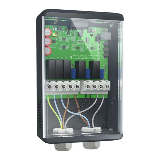
Mains connection (grid) House connection (off-grid) Mains connection (grid) House connection (off-grid) Mains connection (grid) House connection (off-grid) Mains connection (grid) House connection (off-grid) Earth potential House connection Mains connection Earthing PE Fig. 7: Mains connection with cable feedthrough and assignment 7.4. -
Page 26: Installation
Communication RS485 Fig. 8: Communication cable (RJ45) 7.5. Installation Electrician The component is set to switch the grid and off-grid side of the connections in the delivery state. The component is activated when the SolBrid hybrid inverter is started. The component is ready for operation when the green LED on the circuit board lights up. -
Page 27: Maintenance And Troubleshooting
Operating status display Green = component is ready for operation => communication & supply to the inverter available Red = there is a fault => supply is available but communication is not working Off = no/insufficient power supply Maintenance and troubleshooting DANGER Dangerous voltage due to two operating voltages! Severe injuries or death from contact with the wires... -
Page 28: Errors
CAUTIOUS Damage to the housing parts when using cleaning supplies! If the component is dirty, clean the housing and the housing cover only with a dry cloth. NOTE The cleaning intervals must be adapted to the environmental conditions of the installation site. 9.3. -
Page 29: Shutdown For Troubleshooting
Check that the component is correctly connected to the power supply and grounded. Off = no/insufficient power supply The SolBrid hybrid inverter supplies power to the component via the communication cable. Cause/Solution: 1. The SolBrid Hybrid Inverter is not operating. 2. -
Page 30: Manual Reset Of The Mains Relays
a. Carefully press the retaining tab on the RJ45 connector downwards. b. Remove RJ45 plug from socket. Switch off the mains voltage by deactivating the external fuse elements. 9.5. Manual reset of the mains relays Electrician In exceptional cases, it may be necessary to reset the mains relays so that the power supply to the local installation can be restored via the public power grid. - Page 31 S500 XS500 Fig. 9 Resetting the relays...
-
Page 32: Decommissioning And Dismantling
Decommissioning and dismantling 10.1. Switch off component see chapter 9.4 Shutdown for troubleshooting 10.2. Uninstall component Electrician DANGER Even after the component has been disconnected and switched off, life-threatening voltages remain present at the connections and cables in the housing! Severe injuries or death due to contact with the cables and/or terminals/busbars in the component. -
Page 33: Dismantle Component
10.3. Dismantle component ↻ Component must be electrically uninstalled beforehand (see chapter 10.2). 1. Unscrew the component from the wall using the four screws [ A_2,5]. 2. Hold the cover plate on the housing and carefully snap the upper and lower plastic hinges into place. 10.4. -
Page 34: Disposal
Disposal CAUTIOUS Environmental damage if not disposed properly! Both the component and the associated transport packaging are made largely from recyclable raw materials. Defective components and accessories do not belong in the household waste. Make sure that the old device and any accessories are disposed of properly. -
Page 35: Service And Warranty
2. Specify the component that is probably the cause of the problem. 3. Error display of the LEDs, error description, abnormalities. 4. What has already been done to analyze the error? The current warranty conditions of Kontron Solar GmbH can be found in the download area at www.kontron-solar.com. - Page 36 Kontron Solar GmbH - Mammostr. 1 – 87700 Memmingen – Germany - www.kontron-solar.com...
Need help?
Do you have a question about the Solar hy-switch and is the answer not in the manual?
Questions and answers