Advertisement
Quick Links
Advertisement

Related Manuals for Joyonway P15B66

Summary of Contents for Joyonway P15B66
- Page 1 P15B66 Quick installation guide English V1.0...
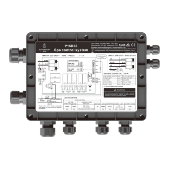
- Page 2 English thermostat light power input control panel pump2 cycle pump DC ozone pump1 temperature sensor heater pump3 and blower AC ozone aux power output Configure and connect the loads, when the system is powered off Configure dial switch position A1-A5 according to the dial switch S1 configuration table (figure on the right) on the control system PCB.
-
Page 3: Load Configuration
English Load configuration A1 (RGB light function set) ON▲:four lines RGB lights. OFF▼:two lines lights. A2:(power limit set) ON▲ : when the power limit is in effect,heating and pump (double speed pump in high speed) can not work at the same time. power not limit OFF▼: A3:(CN9 output function set)... - Page 4 English Connect the main power (when the control system is powered off ) Locate the jumper position BROWN Voltage input:220-240V~ BLUE 50Hz 1P*32A Jumper position J3-J5 Y LW / G R N BROWN Voltage input:220-240V~ N1/N2 BLUE 50Hz 2P*16A Jumper position BROWN YLW/GRN...
-
Page 5: After Sales Service
AFTER-SALES SERVICE : www.joyonway.eu...
Need help?
Do you have a question about the P15B66 and is the answer not in the manual?
Questions and answers