
Summary of Contents for JFA Electronicos AP400
- Page 1 Audio amplifier Amplificadores de audio AP400 e AP800 INSTRUCTION MANUAL MANUAL DE INSTRUCCIONES...
-
Page 2: Table Of Contents
AP400 AND AP800 AUDIO AMPLIFIER - INSTRUCTION MANUAL SUMMARY PRESENTATION ................1 INSTALLATION SAFETY ..............2 SUMMARY OF THE MAIN FEATURES AND FUNCTIONS ................3 CONNECTIONS AND CONTROL............5 OPERATING MODES OF THE FUNCTIONS ................ 6 CONNECTIONS ................9 TECHNICAL SPECIFICATION ............ -
Page 3: Presentation
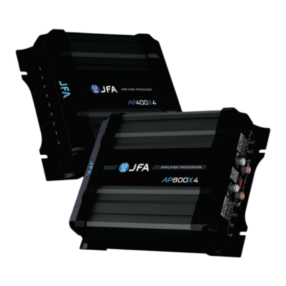
AP400 AND AP800 AUDIO AMPLIFIER - INSTRUCTION MANUAL 1. PRESENTATION The AP400X4, AP800X4 ampliers from JFA are a range of class D multichannel ampliers with a robust and compact design, high power and high performance, developed to meet the need for compact, versatile ampliers with superior audio quality. -
Page 4: Installation Safety
AP400 AND AP800 AUDIO AMPLIFIER - INSTRUCTION MANUAL 2. INSTALLATION SAFETY • Installation should always be carried out by a qualied professional. • Before starting the installation, always read the instruction manual carefully. • The amplier must be installed in a rm, ventilated and dry place. -
Page 5: Summary Of The Main Features And Functions
AP400 AND AP800 AUDIO AMPLIFIER - INSTRUCTION MANUAL It is important that the power cables are as short as possible; ◦ • This amplier can produce high levels of sound pressure. To prevent permanent hearing loss, avoid continuous exposure to levels above 85dB (Federal Law 11.291/06). - Page 6 AP400 AND AP800 AUDIO AMPLIFIER - INSTRUCTION MANUAL JFA Intelligent LED: The JFA INTELLIGENT LED is positioned under the JFA logo and is responsible for informing the user of the JFA amplier's operating status. On the AP400X4 and AP800X4 models, the LED is switched on as soon as the amplier receives the Remote Control signal,...
-
Page 7: Connections And Control
AP400 AND AP800 AUDIO AMPLIFIER - INSTRUCTION MANUAL 4. CONNECTIONS AND CONTROLS 1, 2, 3 and 4 - RCA connection: RCA audio input connection for channels 1 to 4 respectively. Connect to the player's audio outputs. 5 and 6 - Crossover: High PASS (HP) lter: settings from 20Hz to 9kHz. -
Page 8: Operating Modes Of The Functions
AP400 AND AP800 AUDIO AMPLIFIER - INSTRUCTION MANUAL 11 - SPEAKER output connection, power supply connection and remote control connection. 12 - Plastic protection for Water Cooler connection (OPTIONAL): connection cap for use with Water Cooler systems. 13 - Fixing points: robust system that allows xing to the metal chassis. - Page 9 AP400 AND AP800 AUDIO AMPLIFIER - INSTRUCTION MANUAL 5.2. CROSSOVER With the help of the Crossover Adjustment Selector, shown above, it is possible to set the lter cut-off points in a much more complete way, customizing the audio output. The lters (HP and LP) should be adjusted taking into account the frequency response of the loudspeakers used, as many of them are sensitive to a very sharp deection of the membrane,...
- Page 10 AP400 AND AP800 AUDIO AMPLIFIER - INSTRUCTION MANUAL LOW PASS (LP) FILTER: By setting the LP (Low Pass Filter) crossover adjustment selector to position X1, the l o w pass input lter setting can be varied between the xed frequency values of 60Hz, 80Hz, 120Hz, 220Hz, 500Hz, 900Hz, 1.2kHz and 2kHz, determining the end of the...
-
Page 11: Connections
AP400 AND AP800 AUDIO AMPLIFIER - INSTRUCTION MANUAL 6. CONNECTIONS To access the output connection for the speakers or to access the input connection for the power supply and remote control, you need to remove the protective cover using a No. 1 Philips screwdriver. - Page 12 AP400 AND AP800 AUDIO AMPLIFIER - INSTRUCTION MANUAL To use the water cooler system, unscrew the 4 plastic water cooler guards (on the sides of the amplier) using a No. 8 screwdriver. Use a 1/8" BSP male quick-connect connector (with oring ring seal) and tubing compatible with the connector purchased.
- Page 13 AP400 AND AP800 AUDIO AMPLIFIER - INSTRUCTION MANUAL 6.2. RCA CONNECTION Using any amplier with a higher amplitude input signal signicantly improves the signal-to-noise ratio. Signal Power Input signal - HIGH Input signal - LOW Noise Floor Time For situations where the amplier is set incorrectly, for example, if the setting is made so that at 50% of the player's volume, the amplier...
- Page 14 AP400 AND AP800 AUDIO AMPLIFIER - INSTRUCTION MANUAL 6.3. SPEAKER OUTPUT AND DC INPUT CONNECTION Using larger-gauge speaker connection cables improves the damping factor (the amplier's ability to control the speaker coil), allowing for a "drier" sound at low frequencies.
- Page 15 AP400 AND AP800 AUDIO AMPLIFIER - INSTRUCTION MANUAL 1 Power connection: Connect the positive (+) terminal directly to the positive pole of the batteries and the negative (-) terminal directly to the negative pole of the battery. The REM terminal is used for remote control and must be connected to the player's REMOTE output.
- Page 16 AP400 AND AP800 AUDIO AMPLIFIER - INSTRUCTION MANUAL Parallel connection 4 OHMS 4 OHMS Resulting impedance: 2 OHMS 8 OHMS 8 OHMS Resulting impedance: 4 OHMS 2 OHMS 2 OHMS Resulting impedance: 4 OHMS ATTENTION: If tweeters are used, depending on the type of connection made, it may be necessary to add passive lters to...
-
Page 17: Connection Diagram
AP400 AND AP800 AUDIO AMPLIFIER - INSTRUCTION MANUAL 6.4. CONNECTION DIAGRAM ATTENTION: If your CD/DVD player does not have 4 RCA outputs, use "Y" cables to connect the 4 inputs. 13 It is mandatory to install protective fuses or circuit... - Page 18 AP400 AND AP800 AUDIO AMPLIFIER - INSTRUCTION MANUAL 3 CHANNELS (STEREO + BRIDGED) 4 OHMS 4 OHMS Subwoofer 4 OHMS 4 OHMS 4 OHMS...
- Page 19 AP400 AND AP800 AUDIO AMPLIFIER - INSTRUCTION MANUAL 2 CHANNELS (BRIDGED)
-
Page 20: Technical Specification
AP400 AND AP800 AUDIO AMPLIFIER - INSTRUCTION MANUAL 7. TECHNICAL SPECIFICATIONS MODEL AP 400x4 AP 800x4 Number of channels Maximum power 13.8Vdc - 2Ohm* 400W RMS (4x95WRMS) 800W RMS (4x200W RMS) Maximum power 13.8Vdc - 4Ohm* 252W RMS (4x63WRMS) 504W RMS ( 4x504WRMS) Maximum bridged power 13.8Vdc -... -
Page 21: Warranty Certificate
AP400 AND AP800 AUDIO AMPLIFIER - INSTRUCTION MANUAL 8. WARRANTY CERTIFICATE The JFA Eletrônicos warranty period is 3 (three) months legal warranty 9 (nine) months warranty granted by JFA Eletrônicos, totaling 1 (one) year warranty. The warranty is against manufacturing defects and is valid from the date of sale to the nal consumer. -
Page 22: Presentación
AMPLIFICADOR DE AUDIO AP400 Y AP800 - MANUAL DE INSTRUCCIONES 1. PRESENTACIÓN Los amplicadores AP400X4, AP800X4 de JFA son una gama de amplicadores multicanal de clase D con un diseño robusto y compacto, gran potencia y alto rendimiento, desarrollados para satisfacer la necesidad de amplicadores compactos y versátiles con una calidad de... -
Page 23: Seguridad De La Instalación
AMPLIFICADOR DE AUDIO AP400 Y AP800 - MANUAL DE INSTRUCCIONES 2. SEGURIDAD DE LA INSTALACIÓN • La instalación debe realizarla siempre un profesional cualicado. • Antes de iniciar la instalación, lea siempre atentamente el manual de instrucciones. • El amplicador debe instalarse en un lugar rme, ventilado y seco. -
Page 24: Resumen De Las Principales Característicasy Funciones
AMPLIFICADOR DE AUDIO AP400 Y AP800 - MANUAL DE INSTRUCCIONES Es muy importante utilizar el calibre de cable correcto para ◦ obtener la potencia deseada del amplicador y por razones de seguridad. El uso de calibres inferiores a los especicados provoca la pérdida de potencia y el sobrecalentamiento de... - Page 25 AMPLIFICADOR DE AUDIO AP400 Y AP800 - MANUAL DE INSTRUCCIONES LED Inteligente JFA: El LED INTELIGENTE JFA está situado bajo el logotipo JFA y se encarga de informar al usuario del estado de funcionamiento del amplicador JFA. En los modelos AP400X4 y AP800X4, el LED se enciende en cuanto el amplicador recibe la señal del...
-
Page 26: Conexiones Y Controles
AMPLIFICADOR DE AUDIO AP400 Y AP800 - MANUAL DE INSTRUCCIONES 4. CONEXIONES Y CONTROLES 1, 2, 3 y 4 - Conexión RCA: Conexión de entrada de audio RCA para los canales 1 a 4 respectivamente. Conectar a las salidas de audio del reproductor. -
Page 27: Modos De Funcionamiento De Las Funciones
AMPLIFICADOR DE AUDIO AP400 Y AP800 - MANUAL DE INSTRUCCIONES 11 - Conexión de salida de los ALTAVOCES, conexión de alimentación y conexión del mando a distancia. 12 - Protección de plástico para la conexión Water Cooler (OPCIONAL): tapa de conexión para el uso de sistemas Water Cooler. - Page 28 AMPLIFICADOR DE AUDIO AP400 Y AP800 - MANUAL DE INSTRUCCIONES 5.2. CROSSOVER Con la ayuda del Selector de Ajuste de Crossover, mostrado arriba, es posible ajustar los puntos de corte de los ltros de una forma mucho más completa, personalizando la salida de audio. Los ltros (HP y LP) deben ajustarse teniendo en cuenta la respuesta en frecuencia de los altavoces utilizados, ya que muchos de ellos son sensibles a una deexión...
- Page 29 AMPLIFICADOR DE AUDIO AP400 Y AP800 - MANUAL DE INSTRUCCIONES FILTRO DE PASO BAJO (LP): Colocando el selector de ajuste del crossover LP (ltro de paso bajo) en la posición X1, el ajuste del ltro de entrada de paso bajo puede variarse entre los valores de frecuencia jos de 60Hz, 80Hz, 120Hz, 220Hz, 500Hz, 900Hz, 1,2kHz y 2kHz, determinando el extremo de la gama de frecuencias en la que funcionará...
-
Page 30: Conexiones
AMPLIFICADOR DE AUDIO AP400 Y AP800 - MANUAL DE INSTRUCCIONES 6. CONEXIONES Para acceder a la conexión de salida para los altavoces o para acceder a la conexión de entrada para la fuente de alimentación y el mando a distancia, es necesario retirar la cubierta protectora utilizando un destornillador Philips nº... - Page 31 AMPLIFICADOR DE AUDIO AP400 Y AP800 - MANUAL DE INSTRUCCIONES Para utilizar el sistema de refrigeración por agua, desenrosque los 4 protectores de plástico del refrigerador de agua (situados en los laterales del amplicador) con un destornillador N°8. Utilice un conector macho de conexión rápida de 1/8"...
- Page 32 AMPLIFICADOR DE AUDIO AP400 Y AP800 - MANUAL DE INSTRUCCIONES 6.2. CONEXIÓN RCA El uso de cualquier amplicador con una señal de entrada de mayor amplitud mejora signicativamente la relación señal/ruido. Potencia de la señal Señal de entrada - ALTA Señal de entrada - BAJA...
- Page 33 AMPLIFICADOR DE AUDIO AP400 Y AP800 - MANUAL DE INSTRUCCIONES 6.3. CONEXIÓN DE SALIDA DE ALTAVOZ Y ENTRADA DE C.C. El uso de cables de conexión de altavoces de mayor calibre mejora el factor de amortiguación (la capacidad del amplicador para controlar la bobina del altavoz), lo que permite obtener un sonido más "seco"...
- Page 34 AMPLIFICADOR DE AUDIO AP400 Y AP800 - MANUAL DE INSTRUCCIONES 1 Conexión de alimentación: Conecte el terminal positivo (+) directamente al polo positivo de las pilas y el terminal negativo (-) directamente al polo negativo de las pilas. El terminal REM se utiliza para el mando a distancia y debe conectarse a la salida REMOTE del reproductor.
- Page 35 AMPLIFICADOR DE AUDIO AP400 Y AP800 - MANUAL DE INSTRUCCIONES Conexión en paralelo 4 OHMS 4 OHMS Impedancia resultante 2 OHMS 8 OHMS 8 OHMS Impedancia resultante 4 OHMS 2 OHMS 2 OHMS Impedancia resultante 4 OHMS ATENCIÓN: Si se utilizan tweeters, dependiendo del tipo de conexión realizada, puede ser necesario añadir ltros pasivos...
-
Page 36: Esquema De Conexión
AMPLIFICADOR DE AUDIO AP400 Y AP800 - MANUAL DE INSTRUCCIONES 6.4. ESQUEMA DE CONEXIÓN ATENCIÓN: Si su reproductor de CD/DVD no dispone de 4 salidas RCA, utilice cables "Y" para conectar las 4 entradas. Es obligatorio instalar fusibles o disyuntores de... - Page 37 AMPLIFICADOR DE AUDIO AP400 Y AP800 - MANUAL DE INSTRUCCIONES 3 CANALES (ESTÉREO + PUENTE) 4 OHMS 4 OHMS Subwoofer 4 OHMS 4 OHMS 4 OHMS...
- Page 38 AMPLIFICADOR DE AUDIO AP400 Y AP800 - MANUAL DE INSTRUCCIONES 2 CANALES (PUENTEADOS)
-
Page 39: Especificaciones Técnicas
AMPLIFICADOR DE AUDIO AP400 Y AP800 - MANUAL DE INSTRUCCIONES 7. ESPECIFICACIONES TÉCNICAS MODELO AP 400x4 AP 800x4 Número de canales Potencia máxima 13,8Vcc - 2Ohm* 400W RMS (4x95WRMS) 800W RMS (4x200W RMS) Potencia máxima 13,8Vcc - 4Ohm* 252W RMS (4x63WRMS) 504W RMS ( 4x504WRMS) Potencia máxima en puente 13,8Vdc... -
Page 40: Certificado De Garantía
AMPLIFICADOR DE AUDIO AP400 Y AP800 - MANUAL DE INSTRUCCIONES 8. CERTIFICADO DE GARANTÍA El período de garantía de JFA Eletrônicos es de 3 (tres) meses de garantía legal 9 (nueve) meses de garantía concedida por JFA Eletrônicos, totalizando 1 (un) año de garantía. - Page 41 jfaeletronicos.com @jfaeletronicos jfaeletronicos...
Need help?
Do you have a question about the AP400 and is the answer not in the manual?
Questions and answers
What is hole pattern dimensions