Table of Contents
Advertisement
Quick Links
Advertisement
Table of Contents

Subscribe to Our Youtube Channel
Related Manuals for marvelTech VM II Elite 6K Hybrid


Summary of Contents for marvelTech VM II Elite 6K Hybrid
- Page 1 VM II Elite 6K Hybrid User Manual...
-
Page 2: Table Of Contents
Table Of Contents ABOUT THIS MANUAL ............................1 Purpose ................................1 Scope ................................1 SAFETY INSTRUCTIONS ........................... 1 INTRODUCTION ..............................2 Features ................................2 Basic System Architecture ..........................2 Product Overview ............................. 3 INSTALLATION ..............................4 Unpacking and Inspection ..........................4 Preparation .............................. -
Page 3: About This Manual
ABOUT THIS MANUAL Purpose This manual describes the assembly, installation, operation and troubleshooting of this unit. Please read this manual carefully before installations and operations. Keep this manual for future reference. Scope This manual provides safety and installation guidelines as well as information on tools and wiring. SAFETY INSTRUCTIONS All safety instructions in this document must be read, understood and WARNING:... -
Page 4: Introduction
INTRODUCTION This is a multi-function inverter, combining functions of inverter, solar charger and battery charger to offer uninterruptible power support in a single package. The comprehensive LCD display offers user-configurable and easy-accessible button operations such as battery charging current, AC or solar charging priority, and acceptable input voltage based on different applications. -
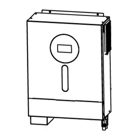
Page 5: Product Overview
Product Overview 1. LCD display 2. Function buttons with status indication 3. Power on/off switch 4. AC input 5. AC output 6. PV input 7. Battery input 8. Circuit breaker 9. BMS communication port 10. RS-232 communication port... -
Page 6: Installation
INSTALLATION Unpacking and Inspection Before installation, please inspect the content. Be sure that nothing inside the package is damaged. You should have received the following items inside the package: Inverter x 1 User manual x 1 RS232 Communication cable x 1 Software CD x 1 DC Fuse x 1 PV connectors x 1 set... -
Page 7: Battery Connection
Install the unit by screwing two screws. It’s recommended to use M4 or M5 screws. Battery Connection CAUTION: For safety operation and regulation compliance, it’s requested to install a separate DC over-current protector or disconnection device between battery and the inverter. It may not be necessary to have a disconnection device in some applications, however, it’s still recommended to have over-current protection installed. - Page 8 Refer to battery cable size for torque value. Make sure polarity at both the battery and the inverter is correctly connected and ring terminals are secured to the battery terminals. WARNING: Shock Hazard Installation must be performed with care due to high battery voltage in series. CAUTION!! Do not place anything between inverter terminals and the ring terminals.
-
Page 9: Ac Input/Output Connection
AC Input/Output Connection CAUTION!! Before connecting to AC input power source, please install a separate AC breaker between the inverter and the AC input power source. This will ensure that the inverter can be safely disconnected during maintenance and fully protected from over-current. The recommended spec of AC breaker is 32A CAUTION!! There are two power terminal blocks with “IN”... -
Page 10: Pv Connection
5. Make sure the wires are securely connected. CAUTION: Appliances such as air conditioner required at least 2~3 minutes to spool up because it needs to have enough time to balance refrigerant gas inside of circuits. If a power shortage occurs and recovers in a short period of time, it may cause damage to your connected appliances. - Page 11 Prepare the cable and follow the connector assembly process: Strip one cable 8 mm on both end sides and be careful NOT to nick conductors. Insert striped cable into female terminal and crimp female terminal as shown below. Insert assembled cable into female connector housing as shown below. Insert striped cable into male terminal and crimp male terminal as shown below.
-
Page 12: Final Assembly
Take 250Wp PV module as an example. After considering above two parameters, the recommended module configurations are listed as below table. Solar Panel Spec. SOLAR INPUT Total input Q'ty of panels (reference) Min in series: 6 pcs, max. in series: 12 pcs. power - 250Wp 6 pcs in series... -
Page 13: Communication Connection
Communication Connection Serial Connection Please use supplied communication cable to connect to inverter and PC. Insert bundled CD into a computer and follow on-screen instruction to install the monitoring software. For the detailed software operation, please check user manual of software inside of CD. Optional Wi-Fi Connection You may separately purchase the inverter with Wi-Fi transmitter. -
Page 14: Operation
OPERATION Power ON/OFF Once the unit has been properly installed and the batteries are connected well, simply press On/Off switch (located on the side of the inverter) to turn on the unit. Operation and Display Panel The operation and the LCD module, shown in the chart below, includes four touchable buttons with status indication and a LCD display, indicating the operating status and input/output power information. -
Page 15: Lcd Display Icons
LCD Display Icons Icon Function description Input Source Information Indicates the AC input. Indicates the PV input Indicate input voltage, input frequency, PV voltage, charger current, charger power, battery voltage. Configuration Program and Fault Information Indicates the setting programs. Indicates the warning and fault codes. Warning: flashing with warning code. - Page 16 In battery mode, it will present battery capacity. Load Percentage Battery Voltage LCD Display < 1.85V/cell 1.85V/cell ~ 1.933V/cell Load >50% 1.933V/cell ~ 2.017V/cell > 2.017V/cell < 1.892V/cell 1.892V/cell ~ 1.975V/cell Load < 50% 1.975V/cell ~ 2.058V/cell > 2.058V/cell Load Information Indicates overload.
-
Page 17: Lcd Setting
LCD Setting After pressing and holding ENTER button for 3 seconds, the unit will enter setting mode. Press “UP” or “DOWN” button to select setting programs. And then, press “ENTER” button to confirm the selection or ESC button to exit. Setting Programs: Progra Description... - Page 18 User-Defined If “User-Defined” is selected, battery charge voltage and low DC cut-off voltage can be set up in program 26, 27 and 29. Pylontech battery If selected, programs of 02, 26, 27 and 29 will be automatically set up. No need for further setting. WECO battery If selected, programs of 02, 12, 26, 27 and 29 will be auto-configured...
- Page 19 240V Output voltage Maximum utility charging Utility charging current: 30A Generator charging current: 30A current (default) (default) Note: If setting value in program 02 is smaller than that in program in 11, the Setting range is 2A, then from 10A to 100A. Increment of each inverter will apply charging current from program 02 for click is 10A.
- Page 20 Alarm on (default) Alarm off Alarm control Return to default display If selected, no matter how users screen (default) switch display screen, it will automatically return to default display screen (Input voltage Auto return to default display /output voltage) after no button is screen pressed for 1 minute.
- Page 21 Low DC cut-off voltage or If any type of lithium battery is SOC 0% (default for lithium SOC: selected in program 05, setting battery) If battery power is only value will change to SOC power source available, automatically. Adjustable range is inverter will shut down.
-
Page 22: Display Setting
Setting range is disable and then Disable (Default) from 0 min to 990 min. Increment of each click is 5 min. Setting discharge time on the *If the battery discharge time achieves setting time second output program 61 and the program 60 function is not triggered, the second output will be turned off. -
Page 23: Selectable Information
Selectable information LCD display Input Voltage=230V, output voltage=230V Power source= Utility Input voltage/Output voltage (Default Display Screen) NOTE: If any warning or fault occurs, it will Input Voltage=230V, output voltage=230V show warning/fault code first. Power source= Generator Input frequency=50Hz, Power source= Utility Input frequency NOTE: If any warning or fault occurs, it will Input frequency=50Hz, Power source= Generator... - Page 24 Selectable information LCD display AC and PV charging current=50A Charging Current PV charging current=50A AC charging current=50A Charging current AC and PV charging power=500W Charging power PV charging power=500W AC charging power=500W Charging power Battery voltage=55.5V, output voltage=230V Battery voltage and output voltage Output frequency=50Hz Output frequency...
- Page 25 Selectable information LCD display Load percent=70% Load percentage When connected load is lower than 1kVA, load in VA will present xxxVA like below chart. Load in VA When load is larger than 1kVA ( 1KVA), load in VA will present x.xkVA like below chart. When load is lower than 1kW, load in W will present xxxW like below chart.
-
Page 26: Operating Mode Description
Selectable information LCD display Main CPU version 00014.04 Main CPU version checking Second CPU version 00014.04 Second CPU version checking Third CPU version 00001.02 Third CPU version checking Operating Mode Description Operation mode Description LCD display Charging by utility and PV energy. Charging by utility. - Page 27 Operation mode Description LCD display Charging by utility and PV energy. Charging by utility. If “solar first” is selected as output source priority and solar energy is not sufficient to provide the load, solar energy and the utility will The unit will provide output provide the loads and charge the battery at the same time.
-
Page 28: Battery Equalization Description
Battery Equalization Description Battery equalization function is built into the charge controller. It reverses the buildup of negative chemical effects such as stratification, a condition where acid concentration is greater at the bottom of the battery than at the top. Equalization also helps to remove sulfate crystals that may have built up on the plates. If left unchecked, this condition, called sulfation, will reduce the overall capacity of the battery. -
Page 29: Fault Reference Code
Fault Reference Code Fault Code Fault Event Icon on Fan is locked when inverter is off. Over temperature or NTC is not connected well. Battery voltage is too high Battery voltage is too low Output short circuited or over temperature is detected by internal converter components. -
Page 30: Warning Indicator
Warning Indicator Warning Warning Event Audible Alarm Icon flashing Code Beep three times every Fan is locked when inverter is on. second Over temperature None Battery is over-charged Beep once every second Low battery Beep once every second Overload Beep once every 0.5 second Output power derating Beep twice every 3 seconds PV energy is low. -
Page 31: Clearance And Maintenance For Anti-Dust Kit
CLEARANCE AND MAINTENANCE FOR ANTI-DUST KIT Overview Every inverter is already installed with anti-dusk kit from factory. This kit keeps dusk from your inverter and increases product reliability in harsh environment. Clearance and Maintenance Step 1: Please loosen the screw on the side of the inverter. Step 2: Then, dustproof case can be removed and take out air filter foam as shown in below chart. -
Page 32: Specifications
SPECIFICATIONS Table 1 Line Mode Specifications MODEL Input Voltage Waveform Sinusoidal (utility or generator) Nominal Input Voltage 230Vac 170Vac±7V (UPS); Low Loss Voltage 90Vac±7V (Appliances) 180Vac±7V (UPS); Low Loss Return Voltage 100Vac±7V (Appliances) High Loss Voltage 280Vac±7V High Loss Return Voltage 270Vac±7V Max AC Input Voltage 300Vac... -
Page 33: Overload Protection
Table 2 Inverter Mode Specifications MODEL Rated Output Power 6KVA/6KW Output Voltage Waveform Pure Sine Wave Output Voltage Regulation 230Vac±5% 50Hz Output Frequency Peak Efficiency Overload Protection ; 10s@105%~130% load Surge Capacity 2* rated power for 5 seconds Nominal DC Input Voltage 48Vdc Cold Start Voltage 46.0Vdc... - Page 34 Table 3 Charge Mode Specifications Utility Charging Mode MODEL Charging Current (UPS) 100Amp(@V =230Vac) @ Nominal Input Voltage Flooded Battery 58.4Vdc Bulk Charging Voltage AGM / Gel Battery 56.4Vdc Floating Charging Voltage 54Vdc Charging Algorithm 3-Step Battery Voltage, per cell Charging Current, % 2.43Vdc (2.35Vdc) Voltage...
-
Page 35: Trouble Shooting
TROUBLE SHOOTING Problem LCD/LED/Buzzer Explanation / Possible cause What to do Unit shuts down LCD/LEDs and buzzer automatically will be active for 3 The battery voltage is too low 1. Re-charge battery. during startup seconds and then (<1.91V/Cell) 2. Replace battery. process. -
Page 36: Appendix I: Bms Communication Installation
Appendix I: BMS Communication Installation 1. Introduction If connecting to lithium battery, it is recommended to purchase a custom-made RJ45 communication cable. Please check with your dealer or integrator for details. This custom-made RJ45 communication cable delivers information and signal between lithium battery and the inverter. - Page 37 PYLONTECH Dip Switch: There are 4 Dip Switches that sets different baud rate and battery group address. If switch position is turned to the “OFF” position, it means “0”. If switch position is turned to the “ON” position, it means “1”.
- Page 38 Step 2: Use supplied RJ45 cable (from battery module package) to connect inverter and Lithium battery. Note for parallel system: 1. Only support common battery installation. 2. Use custom-made RJ45 cable to connect any inverter (no need to connect to a specific inverter) and Lithium battery.
- Page 39 PYLONTECH After configuration, please install LCD panel with inverter and Lithium battery with the following steps. Step 1. Use custom-made RJ45 cable to connect inverter and Lithium battery. Step 2. Switch on Lithium battery. Step 3. Press more than three seconds to start Lithium battery. Output power is ready. Step 4.
- Page 40 WECO Step 1. Use a custom-made RJ45 cable to connect inverter and Lithium battery. Step 2. Switch on Lithium battery. Step 3. Turn on the inverter. Step 4. Be sure to select battery type as “WEC” in LCD program 5. If communication between the inverter and battery is successful, the battery icon on LCD display will “flash”.
-
Page 41: Lcd Display Information
Step 2. Open DC isolator and switch on Lithium battery. Step 3. Turn on the inverter. Step 4. Be sure to select battery type as “SOL” in LCD program 5. If communication between the inverter and battery is successful, the battery icon on LCD display will “flash”. - Page 42 6. Code Reference Related information code will be displayed on LCD screen. Please check inverter LCD screen for the operation. Code Description If battery status is not allowed to charge and discharge after the communication between the inverter and battery is successful, it will show code 60 to stop charging and discharging battery.
-
Page 43: Appendix Ii: Wi-Fi Operation Guide (Optional)
Appendix II: Wi-Fi Operation Guide (optional) 1. Introduction Wi-Fi module can enable wireless communication between off-grid inverters and monitoring platform. Users have complete and remote monitoring and controlling experience for inverters when combining Wi-Fi module with WatchPower APP, available for both iOS and Android based device. All data loggers and parameters are saved in iCloud. - Page 44 Then, a “Registration success” window will pop up. Tap “Go now” to continue setting local Wi-Fi network connection. Step 2: Local Wi-Fi Module Configuration Now, you are in “Wi-Fi Config” page. There are detailed setup procedure listed in “How to connect?” section and you may follow it to connect Wi-Fi.
- Page 45 Step 3: Wi-Fi Network settings icon to select your local Wi-Fi router name (to access the internet) and enter password. Step 4: Tap “Confirm” to complete the Wi-Fi configuration between the Wi-Fi module and the Internet. If the connection fails, please repeat Step 2 and 3. Diagnose Function If the module is not monitoring properly, please tap “...
- Page 46 2-3. Login and APP Main Function After finishing the registration and local Wi-Fi configuration, enter registered name and password to login. Note: Tick “Remember Me” for your login convenience afterwards. Overview After login is successfully, you can access “Overview” page to have overview of your monitoring devices, including overall operation situation and Energy information for Current power and Today power as below diagram.
- Page 47 Devices Tap the icon (located on the bottom) to enter Device List page. You can review all devices here by adding or deleting Wi-Fi Module in this page. Add device Delete device (swipe left) icon on the top right corner and manually enter part number to add device. This part number label is pasted on the bottom of remote LCD panel.
- Page 48 2-4. Device List In Device List page, you can pull down to refresh the device information and then tap any device you want to check up for its real-time status and related information as well as to change parameter settings. Please refer to the parameter setting list.
- Page 49 Battery Mode Inverter will power the load from the batter with or without PV charging. Only PV source can charge battery. Device Alarm and Name Modification In this page, tap the icon on the top right corner to enter the device alarm page. Then, you can review alarm history and detailed information.
- Page 50 Rated Information displays information of Nominal AC voltage, Nominal AC current, Rated battery voltage, Nominal output voltage, Nominal output frequency, Nominal output current, Nominal output apparent power and Nominal output active power. Please slide up to see more rated information. History displays the record of unit information and setting timely.
- Page 51 Item Description Output setting Battery Voltage/SOC to To set voltage point or SOC percentage to re-start on second (L2) Turn On L2 output. Charge Time to Turn To set waiting time to on second (L2) output when the inverter is On L2 back to Line Mode or battery is in charging status.
Need help?
Do you have a question about the VM II Elite 6K Hybrid and is the answer not in the manual?
Questions and answers