Advertisement
Quick Links
Advertisement

Related Manuals for hernest HEFTKT-0003


Summary of Contents for hernest HEFTKT-0003
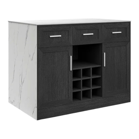
- Page 1 HERNEST HERNEST ASSEMBLY INSTRUCTIONS HEFTKT-0003/HEFTKT-0004...
- Page 2 HERNEST ASSEMBLY INSTRUCTIONS Notice: Follow the installation instructions. Please con fi rm all accessories are preset before installation. Do not fully tighten the screws during initial assembly.Fully tighten screws only once all pieces which are correctly assembled. 3. If you encounter any problems during installation,please contact our customer service.
- Page 3 HERNEST ASSEMBLY INSTRUCTIONS Item Item Reference Image Qty. Reference Image Qty. ×24 ×36 4*14mm *12mm ×1 ×2 4*20mm ×3 ×8 *20mm 4*15mm ×2 ×3 *1mm ×4...
- Page 4 HERNEST ASSEMBLY INSTRUCTIONS Item Item Reference Image Qty. Reference Image Qty. × × × × × × × ×...
- Page 5 HERNEST ASSEMBLY INSTRUCTIONS Item Item Reference Image Qty. Reference Image Qty. × × × × × × × ×...
- Page 6 HERNEST ASSEMBLY INSTRUCTIONS Item Item Reference Image Qty. Reference Image Qty. × × × × × × × ×...
- Page 7 HERNEST ASSEMBLY INSTRUCTIONS Explosion Diagram...
- Page 8 HERNEST ASSEMBLY INSTRUCTIONS × × × × × Screw driver not included. Cam Lock/Dowel Placement Supplement To tighten, turn the Cam Lock CLOCKWISE until the arrow or " " signs point AWAY from the connected Panel. When inserting the Cam lock, make sure that...
- Page 9 HERNEST ASSEMBLY INSTRUCTIONS × × × 10 × × × ×...
- Page 10 HERNEST ASSEMBLY INSTRUCTIONS × × × 10 × × × ×...
- Page 11 HERNEST ASSEMBLY INSTRUCTIONS × × × TURN OVER...
- Page 12 HERNEST ASSEMBLY INSTRUCTIONS × × ×...
- Page 13 HERNEST ASSEMBLY INSTRUCTIONS × × ×...
- Page 14 HERNEST ASSEMBLY INSTRUCTIONS × × × TURN OVER...
- Page 15 HERNEST ASSEMBLY INSTRUCTIONS × × × × ×...
- Page 16 HERNEST ASSEMBLY INSTRUCTIONS × × × ×...
- Page 17 HERNEST ASSEMBLY INSTRUCTIONS 14 × × ×...
- Page 18 HERNEST ASSEMBLY INSTRUCTIONS × ×...
- Page 19 HERNEST ASSEMBLY INSTRUCTIONS ×...
- Page 20 HERNEST ASSEMBLY INSTRUCTIONS 13 × × × ×...
- Page 21 HERNEST ASSEMBLY INSTRUCTIONS × × ×...
- Page 22 HERNEST ASSEMBLY INSTRUCTIONS 12 × × ×...
- Page 23 HERNEST ASSEMBLY INSTRUCTIONS × × × × × × ×...
- Page 24 HERNEST ASSEMBLY INSTRUCTIONS × × × × × × × TURN OVER...
- Page 25 HERNEST ASSEMBLY INSTRUCTIONS 22 × ×...
- Page 26 HERNEST ASSEMBLY INSTRUCTIONS 20 × 17 × 18 × 19 × × ×...
- Page 27 HERNEST ASSEMBLY INSTRUCTIONS 21 × 23 × 24 × × ×...
- Page 28 HERNEST ASSEMBLY INSTRUCTIONS × × 21 23 24 TURN OVER 23 24...
- Page 29 HERNEST ASSEMBLY INSTRUCTIONS...
- Page 30 HERNEST ASSEMBLY INSTRUCTIONS 24 J 16 × × 15 × × × × lnstallation Completed Please refer to hinge adjustment supplement next page.
- Page 31 HINGE ADJUSTMENT SUPPLEMENT OUTSIDE MACHINE SCREW In the event that the door does not align properly, the INSIDE Machine Screws located on the Hinges are for adjusting slightly to the Left or Right. DO NOT LOOSEN THE OUTSIDE MACHINE SCREW FOR ADJUSTMENT. A.
- Page 32 HERNEST ®...
Need help?
Do you have a question about the HEFTKT-0003 and is the answer not in the manual?
Questions and answers