Table of Contents
Advertisement
Quick Links
INVIEW
Firmware 6.x
User Manual
INVIEW MONITORING & CONTROL DEVICE:
•
Manages your Infrastructure
•
Informs the user in case of Issues
•
Minimises Maintenance Expenditures
•
Leverages the possibilities of IoT & Big Data
•
Allows to save on your electricity bill with
Energy Management
CONTROLLERS
Inview Slot
Inview S
Inview X
Inview XC
Copyright ©2024. Construction electroniques & telecommunications S.A.
All rights reserved. The contents in document are subject to change without notice.
The products presented are protected by several international patents and trademarks.
Address: CE+T S.a, Rue du Charbonnage 12, B 4020 Wandre, Belgium
www.cet-power.com - info@cet-power.com
Contact us: www.cet-power.com
|
Follow us on social media:
Version 2.3
Advertisement
Table of Contents

Summary of Contents for CE+T Power Inview Slot
- Page 1 Leverages the possibilities of IoT & Big Data • Allows to save on your electricity bill with Energy Management CONTROLLERS Inview Slot Inview S Inview X Inview XC Copyright ©2024. Construction electroniques & telecommunications S.A. All rights reserved. The contents in document are subject to change without notice.
-
Page 2: Table Of Contents
Inview Slot ..........................Inview S ............................Inview X ............................Inview XC ............................ Inview Widget Page ........................Inview Slot, S, X & XC - Specifications ..................Inview License ........................... Accessories ..........................4.8.1 MBB (Measure Box Battery) .................... 4.8.2 UMB (Universal Measure Box) .................. - Page 3 5.6.6 UMB (Universal Measure Box) - Connections ..............5.6.7 Output Relay Connections ....................5.6.8 Digital Input Connections ....................5.6.9 CAN / ModBus (RS485) Pin Details ................. 5.6.10 Inview S with Bravo and Sierra - System ................ 5.6.11 Inview X with Bravo and Sierra - System ................ 5.6.12 Inview XC with Sierra XC - System .................
- Page 4 12.6.4 Simple examples of custom alarms or data ..............13. Annexe 3: Inview - Software Upgrade ..................... 14. Annexe 4: Hardware Replacement......................14.1 Inview Slot, S, X and XC ....................... 14.2 Accessories - MBB and UMB ....................... 15. Annexe 5: Wiring Diagrams ........................
- Page 5 16. Annexe 6: Auxiliary power supply kit ...................... 16.1 Auxiliary power supply kit with Din Rail ..................16.2 Auxiliary power supply kit - Wiring diagram ................. 17. Annexe 7: Inview Panel Sheets ....................... 17.1 Inview S - Panel Sheets ....................... 17.2 Inview X - Panel Sheet .........................
- Page 6 Release Note: Release date Modified page Version Modifications (DD/MM/YYYY) number 23/04/2021 First release of the manual Added Remote ON/OFF details 27/08/2021 58 - 59 Added boolean expressions 28/09/2021 17 & 19 Updated auxiliary power supply kit part number Added License Options, Din-rail mounting procedure and 16/11/2022 13, 16 &...
-
Page 7: Ce+T Power At A Glance
CE+T Power is committed to providing you with the expertise and resources needed to maximize the performance of your power systems. Thank you for choosing CE+T Power as your partner in advanced power management. Let’s power the future together. – Inview – User Manual – v2.3... -
Page 8: Abbreviations
Abbreviations 2. Abbreviations Alternating current Alarm Direct current DHCP Dynamic Host Configuration Protocol Digital Signal Processor Enhanced Conversion Innovation Enhanced Power Conversion Electro Static Discharge Ethernet HTTP HyperText Transfer Protocol HTTPS Secure HyperText Transfer Protocol Local Access Network Low Voltage Disconnect Measure Box Battery Manual By-pass Main Earth Terminal... -
Page 9: Warranty And Safety Conditions
Warranty and Safety Conditions 3. Warranty and Safety Conditions WARNING: Except Inview XC, the electronics in the power supply system are designed for an indoor, clean environment. When installed in a dusty and/or corrosive environment, outdoor or indoor, it is important to: •... -
Page 10: Installation
Warranty and Safety Conditions 3.3 Installation • This product is intended to be installed only in restricted access areas. • The Inverter System may contain output over current protection in the form of circuit breakers. In addition to these circuit breakers, the user must observe the recommended upstream and downstream circuit breaker requirements as per the local regulations. -
Page 11: Maintenance
Warranty and Safety Conditions 3.4 Maintenance • The converter system/rack can reach hazardous leakage currents. Earthing must be carried out prior to energizing the system. Earthing shall be made according to local regulations. • Prior to any work conducted to a system/unit, make sure that AC input voltage and DC input voltage are disconnected. -
Page 12: Introduction
4.1 Inview Slot Inview Slot is an advanced monitoring and controller unit for Bravo 10 and Sierra 10 power systems. This product is specially designed in 1U height to accommodate in the converter shelf and reduces the additional space in the cabinet. -
Page 13: Inview X
Introduction 4.3 Inview X Inview X is an advanced monitoring and controller unit for Bravo Bravo Sierra 10 Sierra 25 power systems. It allows the user to easily view, access the system information through LCD screen graphic display and web interface. The home screen of both LCD and web interface provides a summary of system power, modules, batteries, and events information. -
Page 14: Inview Widget Page
Introduction 4.5 Inview Widget Page The new generic view for the different Inview Slot, S, and X touch screens, as well as in the web interface. Widget view in Web interface Widget view in LCD Touch screen - InView X, S and Slot (from left to right) 4.6 Inview Slot, S, X &... -
Page 15: Inview License
T602004110 T602004100 T602004200 T602004140 4.7 Inview License Each Inview Slot/S/X/XC has a standard licence by default and it can be upgraded to any of the below licences. Contact your supplier or CE+T for the latest price. S.No License Type Features •... -
Page 16: Accessories
Introduction 4.8 Accessories 4.8.1 MBB (Measure Box Battery) Measure Box Battery is a unit which monitors the battery parameters such as battery voltage, current, temperature and LVD. In addition it contains extended Digital Inputs and Output Relay contacts. It is possible to connect up to three MBB’s in parallel. 4.8.2 UMB (Universal Measure Box) Universal Measure Box is a unit which monitors battery parameters such as battery voltage, current, temperature, and LVD. - Page 17 Introduction Models Measure Box Battery Universal Measure Box Synoptic 1 LED 2 LEDs Mounting DIN Rail 90 x 90 x 68 mm Dimension (W x H x D) 160 x 97 x 38 mm 200 g Weight 240 g Measure Box 48 Vdc version: T602006048 Part number T602006000 Measure Box 90 to 430 Vdc version: T602006380...
-
Page 18: Installation
• All power and signal cables should be routed properly. 5.2 Installing - Inview Slot 1. Place the Inview Slot and slide into the shelf. 2. Push the unit firmly until the controller rear part is engaged correctly with shelf. -
Page 19: Din-Rail Mounting
Installation Mount the panel sheet with screws Connect wires and place the panel sheet in the cabinet Note: To know about panel sheet dimension and cut-out details, refer “17. Annexe 7: Inview Panel Sheets”, page 96. 5.3.2 Din-rail Mounting 1. Place the two clips on the mounting bracket and fix them with M4 x 8 mm screws and washers. 2. -
Page 20: Mounting - Inview
Installation 5.4 Mounting - Inview X Before mounting the Inview X in the system, route all the required connection cables from the system and place near to the Inview X mounting location. 1. Place the Inview X in the panel sheet. 2. -
Page 21: Pole Mounting
5.6.1 Inview Slot - Connections Inview Slot has an ETH port and USB at the front. Output relays, digital inputs, CAN and power connections are present at the rear side of the Inview Slot connected shelf. – Inview – User Manual – v2.3... -
Page 22: Inview S - Connections
• Power: The redundant external auxiliary +12 Vdc and the power consumption is 5W. By default, Inview Slot takes power from DC bus. If DC is not present, it takes +12 V from external Auxiliary power supply converter (AC to DC). -
Page 23: Inview X - Connections
Installation • CE+T COM port is dedicated to establish connection between Inview S and converters. • ) port is used for network connectivity and user can access the system information in the Web Interface and SNMP. The default static IP address is 10.250.250.1/24 (the “/24” indicates the Subnet mask address: 255.255.255.0 ) •... -
Page 24: Inview Xc - Connections
Installation • iso CAN is used for CAN communication. • RS485 is used for Modbus communication. • port is used for internal factory purpose. • Digital Inputs (D1 and D2): Two potential free Digital Inputs are available for customer connections. ƒ... -
Page 25: Mbb (Measure Box Battery) - Connections
Installation For Inview XC, IP65 rated NLINKO connectors must be used. Refer to the below picture for Inview XC connectors’ pin details. PIN DETAILS NOT USED +12 V NOT USED NOT USED NOT USED 12345678 12345678 INVIEW XC PIN DETAILS K2 (NO) K2 (NC) ALARMS... -
Page 26: Umb (Universal Measure Box) - Connections
Installation • Current (I1 to I3) terminal is used to monitor the current of Battery. Ensure the polarity from the shunt while wiring. ƒ I1: battery shunt when a common shunt is used for all strings ƒ I2: string 1 shunt when measuring each battery ƒ... -
Page 27: Digital Input Connections
5.6.8 Digital Input Connections In digital input terminal, the external voltage should not be applied and it is mandatory to connect only like switches. Each digital input terminal in Inview Slot/S/X/XC, and MBB should be connected as per diagram. Digital input terminal 5.6.9 CAN / ModBus (RS485) Pin Details... -
Page 28: Inview X With Bravo And Sierra - System
Installation System with Inview S and UMB RJ45 CE+T COM port RJ45 Cable Shelf Inview S Auxiliary Power supply kit CAN / iso RS485 Power (12 V DC) RS485 (Universal Measure Box) Power For more information about wiring refer “15.4 Inview S with UMB”, page 91. 5.6.11 Inview X with Bravo and Sierra - System In Sierra system, the Inview X, Measure Box Battery and Measure Box DC should be connected as per the following: 1. -
Page 29: Inview Xc With Sierra Xc - System
Installation System with Inview X and UMB RJ45 CE+T COM port RJ45 Cable From Battery Shelf Inview X (48 V) RS485 Power AC to DC Adapter (48 V) RS485 (Universal Measure Box) Power For more information about wiring refer “15.6 Inview X with UMB”, page 93. 5.6.12 Inview XC with Sierra XC - System In Sierra XC module, the Inview X should be connected as per the following: 1. -
Page 30: Overview - Web Interface
Overview - Web Interface 6. Overview - Web Interface The web interface of all the Inview controllers is the same. The Inview web interface allows the user to interact with system, access, configure and modify the system parameters. The below tree provides an overview of the menu structure in the web interface. Note: Widgets varies depending upon the topology selection. -
Page 31: Interface Areas
Overview - Web Interface 6.1 Interface Areas 1 Header 2 Home Page 6.1.1 Header The icons on the header provide quick access to the corresponding pages. 1 Home: Clicking on INVIEW logo goes to the home page from any page you are accessing in the interface. 2 D isplay the date, time and site name of the system. -
Page 32: Home Page
Overview - Web Interface 6.1.2 Home Page The default home page is Widgets to display system information briefly. On the Widgets home page, a maximum of 20 widgets can be configured. To know about configuration, refer to the section 7.9, page 53. Clicking on any widget displays the corresponding details on right side of the page. -
Page 33: Widgets
Overview - Web Interface 6.1.3 Widgets The Inview widgets are identical for the web interface and LCD touch screens. The flexible view can be configured depending on the system topology with the following types of widgets: Source Load are the different convention signs used for the different assets. The conventions of the different assets are listed in the below table. -
Page 34: Web
Overview - Web Interface 6.2 Web page Controls Placing or clicking on it performs the corresponding action. Controls Description Filters: Page displays depending upon the filter selection. Page changes to edit mode and the user can change the parameters. If any parameter value is changed, the edit icon changes to modification icon and displays the list. - Page 35 Overview - Web Interface Controls Description Modifications list: It appears at right side of the “Advanced View” page. This list helps the user to overview the changes and can apply the required parameters. Apply: Clicking on “APPLY” button, the controller accepts all the parameter changes in the modifications list.
-
Page 36: Power System Settings
7. Power System Settings Once system is powered on, the Inview Slot, S, X or XC is up and ready for operation. Configuration and other parameters can be changed using the web interface. Perform the following procedure to configure the system through web interface. -
Page 37: Web Interface - User Account
ƒ Click on “DELETE” button to remove the user account. 7.2.2 LCD Interface - PIN number Inview Slot, S, X and XC LCD interface do not have any user account; the user can view the system details and cannot modify the parameters. -
Page 38: Site Management
Power System Settings 7.3 Site Management 7.3.1 Site Description Go to Advanced View > Site > Description Enter the Site details such as Site description , Location and Contact details . 7.3.2 Date and Time Settings Go to Advanced View > Administration > Time Management Choose any one option from the below. -
Page 39: Network Settings
Power System Settings 7.3.3 Network Settings Advanced View > Site > Configuration Go to Enter the network details such as IP address, Firewall settings, NTP time, web server, and applicable parameters. 7.3.4 Home Page Settings Advanced View > Site > Configuration, To set the Widgets or Dashboard as Home page, go to scroll down to Web Server section. -
Page 40: System Configuration
Power System Settings 7.4 System Configuration To configure the converter systems, In Advanced View, go to Site > Energy System > Converter System > Configuration. 7.4.1 Topology Selection In Advanced View, go to Site > Energy System > Converter System > Configuration > System > Global . -
Page 41: Fallback Mode 1
Power System Settings Topology Supported Parameter Parameter Parameter Parameter Input Output Modules ID CF1071 ID CF1066 ID CF1067 ID CF1074 Inverter (REG Bravo 25, AC load DC / AC only) 20 and 10 Inverter with Bravo 25, AC Input (EPC AC and DC AC load 20 and 10... -
Page 42: Phase Selection
Power System Settings Fallback mode 2: • CF1 Topology: ƒ UPS for AC & DC loads or Rectifier is set • CF1066 Charging Voltage: ƒ Configure the voltage required on DC port in fallback mode. Since the modules do not calculate temperature compensation once communication between the Inview controller and the module is lost. -
Page 43: Converters Configuration
Power System Settings • CF1016: enter the nominal frequency (Note: while configuring the AC phases, the converter should be in OFF mode) 7.4.5 Converters Configuration If the system has more than one converter, it is better to start configuring with one converter on each phase. 1. - Page 44 Power System Settings To get an overview of the converter details, go to Site > Energy System > Converter System > Converter > Dashboard In this page also you can modify the converter ID and Phase number. Other Features: • Blink LED: Clicking on “BLINK LED”...
-
Page 45: Dc Configuration
Power System Settings 7.4.6 DC Configuration Advanced View > Site > Energy System > DC System > Configuration. Go to In the DC Bus section, set the parameters depending upon the DC voltage. The below page is configured to 48 Vdc. 7.5 Battery Configuration The battery page provides access and configures battery parameters such as battery characteristics, LVD, temperature compensation, boost charging, and test. -
Page 46: Measurement Source
Power System Settings 7.5.1 Measurement Source ID CF100 and CF101, Select any one option for battery voltage and current based upon the battery source in the respectively. • Auto Detected : It detects automatically based upon the voltage and current measurement •... -
Page 47: Sensors And Actuators
Power System Settings 7.6 Sensors and Actuators The Sensors and Actuators page contains details of external devices such as MBB / UMB, which are connected through CANBUS, Ethernet or RS485. Go to Advanced View > Site > Sensors and Actuators > Dashboard and set the ID as “MBB -1”. -
Page 48: Mbb Configuration
Power System Settings 7.6.1 MBB Configuration Advanced View > Site> Energy System > DC System > Configuration > Battery Before configuring MBB, go to and in ID CF100 ID CF101 Measurement Source section, make sure the is set to “Single probe” and to “Single shunt”. - Page 49 Power System Settings Current section: select an option for the I1, I2 and I3 from the drop-down list in the ID CF201, CF206 CF211, respectively. • dc1_Load: to measure the current of DC load • dc1_Battery: to measure the current of battery •...
- Page 50 Power System Settings (Sa1: Sensors and Actuators, data501: Data section, Digital input D1 (DA501)) ƒ After selecting the options, click “APPLY AND SAVE” in the modification list • K5 and K6 are configured to latch or non-latch LVD, if used Relay section: select an option for K5 and K6 from “Mode”...
-
Page 51: Manual Bypass Configuration
Power System Settings 5. Digital Inputs ƒ To know LVD status, connect the auxiliary contact to the Digital Input 6. The ID CF526 is to select as “ dc1_LvdState ” The below connection diagram is an example of LVD Auxiliary contact. 7.7 Manual Bypass Configuration The manual by-pass is a manually operated switch, and it is used to transfer the load from normal to by-pass without interruption. -
Page 52: Module Remote On/Off
Power System Settings 7.8 Module Remote ON/OFF The AC and DC output of the system and also each module in the system can be turned ON/OFF in two ways: 1. Remote ON/OFF terminal at rear side of the shelf or on a junction kit for Sierra XC parallelization: will impact only AC output. -
Page 53: Widgets Configuration
Power System Settings 7.9 Widgets Configuration Widgets of different sorts are available. Up to 20 widgets can be configured on the home page. The configuration will appear both on the web interface and the LCD touch screens. Before configuration, ensure the default home page is Widgets. - Page 54 Power System Settings I) Similarly, configure for other remaining Assets. S.No Asset Name Asset Type ID Asset Name ID Asset 1 DE510 DE511 Asset 2 DE520 DE521 Asset 3 DE530 DE531 Asset 4 DE540 DE541 Asset N DE5N0 DE5N1 In the below screen shots, Assets 1, 2, 3 and 4 are assigned for AC Input, Battery, AC Loads and DC Loads, respectively.
- Page 55 Power System Settings Widget Connections: Each asset should be linked to a system node to get the real measurements. The different nodes possible with respect to the types are given in the following table. Choose the one that best matches your widget type among the possible links, depending on your system topology. S.No Widget Type...
- Page 56 Power System Settings Go to Advanced View > Converter System > Description > Asset Connections AC Outputs: In the ID DE501, Select the Asset name from the list connected to the system’s Output, ƒ like AC load or renewable sources. The “AC Loads” is selected in the screen shot above, which is the Asset name of the ID DE531.
-
Page 57: Communication Protocol
Power System Settings ƒ Toggle the Advanced view switch and verify all assigned widgets are configured correctly on the home page. 7.10 Communication Protocol 7.10.1 Modbus Modbus over TCP/IP is available, and it has both read and write mode, which means that Modbus can be used for monitoring and execute actions on the system. - Page 58 Power System Settings Device ID Equipment Inverter System 3 Inverter System 4 DC/DC Converter (Iris) Converter System 1 Converter System 2 Converter System 3 Converter System 4 Energy System 1 Site Sensors And Actuators 1 Sensors And Actuators 2 When the equipment does not exist, it will respond with function code 4: •...
-
Page 59: Snmp
Power System Settings 7.10.2 SNMP This section describes the Management Information Base (MIB) schema design for SNMP V1, V2c and V3 configuration. A MIB schema describes the structure of information served by a Simple Network Management Protocol Subsystem (SNMP) agent. For the SNMP configuration, go to Advanced View >... -
Page 60: Cyber Security
Power System Settings 7.11 Cyber Security 7.11.1 Password Policy Starting from Inview software version 5.5, a new password policy is introduced. The password must be a minimum of eight characters. If the wrong password is entered continuously five times, next time, the Inview restrict to login, and it will allow again only after five minutes. - Page 61 Power System Settings • CF152 (Allow technical downgrade process): Select the “True” option and downgrade the software version to the previous one using the USB key. Contact CE+T for the downgrading process. • CF153 (Allow technical Factory reset process): Select the “True” option and perform the factory reset using USB Key.
-
Page 62: Overview - Lcd Interface
8. Overview - LCD Interface 8.1 Inview Slot - LCD Display Once the system is powered up, the Inview Slot is up and ready for operation. The LCD is a 1.8-inch touch screen and user can only view the system details through the interface. -
Page 63: Menu Structure
Overview - LCD Interface 8.1.2 Menu Structure The home page is the default page in the LCD interface, and other pages are arranged in the below sequence. Inview Slot LCD Interface Widget 01 Widget 02 Widget 03 Widget 04 Widget N... -
Page 64: Inview S - Lcd Interface
Overview - LCD Interface 8.2 Inview S - LCD Interface Inview S LCD interface is a 2.8-inch touch screen. It does not have any user account, the user can only view the system details. The LCD interface is protected with the PIN during any action request. To modify the PIN, refer section 7.2.2, page 37. -
Page 65: Menu Structure
Overview - LCD Interface 8.2.2 Menu Structure The below tree provides an overview of the menu structure in the Inview S LCD interface. Inview S LCD Interface Alarms Settings Widgets Last Events Active Alarms System Clean Mute Display Informations Inventory Buzzer Language IP and MAC Addresses... -
Page 66: Inview X - Lcd Interface
Overview - LCD Interface 8.3 Inview X - LCD Interface Inview X LCD interface is a 7-inch touch screen. Through the LCD interface, the user can view and access the system details. Once the system is powered upon, the Inview X is up and ready for operation. Note: Interface graphics and layout may change based on firmware version. -
Page 67: Menu Structure
Overview - LCD Interface 8.3.1 Menu Structure The below tree provides an overview of the menu structure in the Inview X LCD interface. Inview X LCD Interface Alarms Settings Widgets Last Events Active Alarms System Clean Mute Display Informations Inventory Buzzer Language IP and MAC Addresses... -
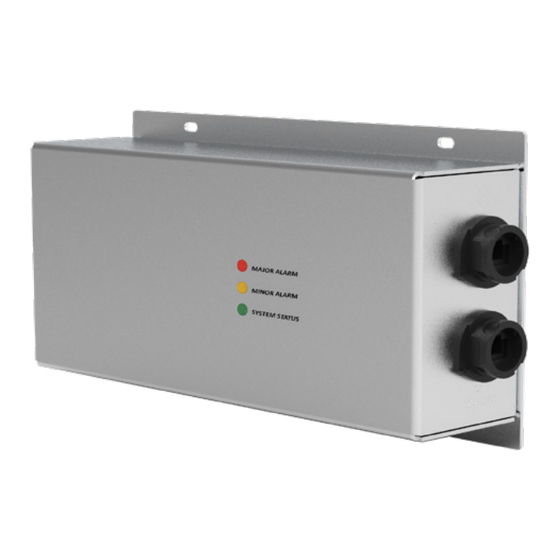
Page 68: Led Indications
Red: Major Alarm Orange: Minor Alarm Green: System status (Normal Operation) 8.5 LCD Interface - Terminology The below table provides the description of terminology which appears in Inview Slot, S and X LCD interface. S.NO Terminology Description The controller performs a complete scan and remove the non-active converters from the converter list. -
Page 69: Defective Unit
ƒ If the warranty is void, the repair costs will be invoiced to the Customer. ƒ If a unit sent back to CE+T Power (Repair or Swap) presents no defect or failure, a lump sum amount will be charged to the Customer. -
Page 70: Trouble Shooting And Service
Trouble shooting and Service 10. Trouble shooting and Service For Service • Check Service Level Agreement (SLA) of your vendor. Most of the time they provide assistance on call with integrated service. If such SLA is in place, you must call their assistance first. •... -
Page 71: Annexe 1: Converter - Parameter List
Annexe 1: Converter - Parameter List 11. Annexe 1: Converter - Parameter List Advanced View > Site > Energy System > Converter System > To view and edit the converter parameters, go to Configuration. If you want to have an overview of standard systems’ parameters, you can also view the parameters in our Monitoring Emulator https://www.cet-power.com/en/monitoring-emulator/. -
Page 72: Annexe 2: Plc/Boolean Expression
Annexe 2: PLC/Boolean Expression 12. Annexe 2: PLC/Boolean Expression 12.1 Overview PLC stands for Programmable Logic Controller. It allows adding custom features (data or alarms) by using some logical expression. It is very cost-effective for regulation where the main loop is not faster than one second. Some configuration elements can be filled with a Boolean expression or a mathematical expression. -
Page 73: Use Of Syntax To Access Data Entries From A Monitored Device
Annexe 2: PLC/Boolean Expression 12.3 Use of syntax to access data entries from a monitored device Syntax Explanation The data with ID XXX of the relative equipment (of the equipment where the PLC is @(daXXX) written). Example: @(data501), @(da501) The data with ID XXX relative to the Energy System with ID Y. @(esY_daXXX) Example: @(es1_da100) –... -
Page 74: Operators & Functions
Annexe 2: PLC/Boolean Expression The highest severity level active, relative to the equipment Sensors And Actuators with @(saY_severity_level) ID Y. 12.5 Operators & functions Syntax Explanation (….) Parentheses && Logical AND Logical OR = or == Equal Not Equal Addition Subtraction Multiplication Division... -
Page 75: Examples Of Boolean Expressions For Custom Plc Data, Alarms And Relays
Annexe 2: PLC/Boolean Expression 12.6 Examples of Boolean Expressions for custom PLC data, alarms and relays 12.6.1 Create a custom data a) Recalculate the voltage of the Converter System AC-out based on apparent power and current. Site > Configuration > PLC I) Go to to add a custom PLC data. -
Page 76: Create A Custom Alarm
Annexe 2: PLC/Boolean Expression 12.6.2 Create a custom alarm a) Adding an overload alarm on an energy meter. I) Go to the concerned Energy Meter > Configuration > PLC II) Change the parameter CF902 (Number Of Custom Alarm) of the energy meter to 1. You will see two new parameters (CF1001, CF1002). - Page 77 Annexe 2: PLC/Boolean Expression b) Adding a high temperature alarm with a hysteresis. I) Go to Site > Configuration > PLC to add a custom PLC alarm. (There is no PLC configuration possible under Sensors and Actuators (MBB, MBHV,...) on which your temperature sensor is cabled.) II) Change the parameter CF902 (Number Of Custom Alarm) to 1.
-
Page 78: Create A Custom Relay
Annexe 2: PLC/Boolean Expression II) Change the parameter CF902 (Number Of Custom Alarm) to 1. You will see two new parameters (CF1001, CF1002). III) Configure the alarm name and triggering condition. ƒ Change the name CF1001 (e.g. “Battery in Charge”) ƒ... - Page 79 Annexe 2: PLC/Boolean Expression III) Configure the alarm name and triggering condition. ƒ Change the name CF1001 (e.g. “Start Genset”) ƒ Change the Boolean expression CF1002 to “(@(da60)<=47)||( @(al601)&&@(da60)<=(@(da18)-0.1)&&(@(da61)<-1||@(da61)>@(da19)/10))”. ○ The alarm will be triggered if @(da60) - the Battery voltage DA60 of the DC System - is less then 47V OR if the alarm is already active (@(al601)) and the Battery voltage DA60 is less than the target voltage -0.1V (@(da60)<=(@(da18)-0.1)) and the measured current is less than -1A (@(da61)<-1) or the measured current is above 10% of the maximum charging current limit (@...
- Page 80 Annexe 2: PLC/Boolean Expression b) Based on a custom expression. I) Go to Site > Configuration > Relay if the relay is on Inview, go to Sensors and Actuators > Configuration > Relay if the relay is on an MBB. Set the mode of the corresponding relay to ‘Custom’. II) Change the Boolean expression to the desired condition.
-
Page 81: Simple Examples Of Custom Alarms Or Data
Annexe 2: PLC/Boolean Expression d) Based on severity type. I) Go to Site > Configuration > Relay if the relay is on Inview, go to Sensors and Actuators > Configuration > Relay if the relay is on an MBB. Set the mode of the corresponding relay to ‘Custom’. II) Change the Boolean expression to the something like “@(dc1_severity_type)>=“major””. - Page 82 Annexe 2: PLC/Boolean Expression Condition or Data Configuration examples • If Redundancy lost alarm need to be configured with relay ƒ Redundancy lost alarm ID from Inview: al103 Linking Specific alarm with Relay ƒ Boolean expression need to be set at relay: @ (convs1_al103) •...
-
Page 83: Annexe 3: Inview - Software Upgrade
Annexe 3: Inview - Software Upgrade 13. Annexe 3: Inview - Software Upgrade User Context > About The current software version number is present on . To know more about software details, go to Controller section. Advanced View > Site > Description and scroll down to the Perform the following steps to upgrade Inview software, and this process can do only through the web interface. - Page 84 Annexe 3: Inview - Software Upgrade 2. Login as admin privileged account in the Inview web interface and go to Administration > Software Update 3. Click “Choose file” button and direct to the downloaded .UPG file and the Click “Upload, save configuration and reboot”...
-
Page 85: Annexe 4: Hardware Replacement
14. Annexe 4: Hardware Replacement 14.1 Inview Slot, S, X and XC Before replacing the new Inview Slot, S, X or XC, the existing configuration file must be saved and need to upload the same after installing the new controller. -
Page 86: Accessories - Mbb And Umb
Annexe 4: Hardware Replacement 14.2 Accessories - MBB and UMB Perform the following steps for replacing MBB and UMB: 1. Remove the existing MBB/UMB from the system. Clear from the inventory list: go to Advanced View> Site > Control , scroll down to the Inventory section. - Page 87 Annexe 4: Hardware Replacement 6. Go to Advanced View > Sensors and Actuators , scroll down to Relay Digital Input section, and verify the mappings are done correctly. – Inview – User Manual – v2.3...
-
Page 88: Annexe 5: Wiring Diagrams
Annexe 5: Wiring Diagrams 15. Annexe 5: Wiring Diagrams 15.1 Inview Slot with MBB OUT OF THE SYSTEM BATTERY TEMP (0.5) 35 37 38 39 52 51 50 49 47 46 45 44 41 40 39 37 36 35 34 33 32 31 30 29 28 27 26 25 24 23 22... -
Page 89: Inview Slot With Umb
Annexe 5: Wiring Diagrams 15.2 Inview Slot with UMB +12Vaux INVIEW C AN S LOT 0Vaux RELAY RELAY DIG IN FROM FROM BATTERY BATTERY SHUNT BATTERY TEMP V2 REF C1 D1 C2 D2 C4 D4 V in A in RS485... -
Page 90: Inview S With Mbb
Annexe 5: Wiring Diagrams 15.3 Inview S with MBB +12Vaux (0,5) 0Vaux IN VIEW CAN / iso RS485 FROM CE+T ECI RACK AUX3 OUT OF THE SYSTEM BATTERY TEMP (0.5 Blk) 53 52 51 50 49 47 46 45 44 41 40 39 37 36 35 34 33 32 31 30 29 28 27 26 25 24 23 22 MEASURE BOX... -
Page 91: Inview S With Umb
Annexe 5: Wiring Diagrams 15.4 Inview S with UMB +12Vaux P W R 0Vaux INVIEW S DIG IN 1 DIG IN 2 FROM ECI RACK +48V AUX +12V AUX POWER SUPPLY POWER SUPPLY FROM FROM BATTERY +48Vaux 0Vaux +12Vaux 0Vaux BATTERY SHUNT BATTERY... -
Page 92: Inview X With Mbb
Annexe 5: Wiring Diagrams 15.5 Inview X with MBB – Inview – User Manual – v2.3... -
Page 93: Inview X With Umb
Annexe 5: Wiring Diagrams 15.6 Inview X with UMB REAR FRONT FROM SHELF INVIEW X RELAYS DIG IN P W R RS485 ISO CAN 48Vdc +48V AUX POWER SUPPLY +48Vaux 0Vaux FROM FROM BATTERY +48VDC BATTERY SHUNT BATTERY TEMP V2 REF C1 D1 C2 D2 C4 D4... -
Page 94: Inview Xc With Mbb
Annexe 5: Wiring Diagrams 15.7 Inview XC with MBB RJ - 4 5 RJ - 4 5 RJ - 4 5 – Inview – User Manual – v2.3... -
Page 95: Annexe 6: Auxiliary Power Supply Kit
Annexe 6: Auxiliary power supply kit 16. Annexe 6: Auxiliary power supply kit 16.1 Auxiliary power supply kit with Din Rail S.No Model Part number 48 Vdc T602004122 110 Vdc T602004124 380 Vdc T602004123 Front View K10 K11 X10 - AC input terminal (1P) X11 - DC input terminal (Battery voltage) X12 - DC Output terminal (12 V DC) X13 - Alarm contact for Aux power... -
Page 96: Annexe 7: Inview Panel Sheets
Annexe 7: Inview Panel Sheets 17. Annexe 7: Inview Panel Sheets 17.1 Inview S - Panel Sheets Dimensions are in mm 3U Panel sheet - cut out details Dimensions are in mm 2U Panel sheet (center)- cut out details Dimensions are in mm 2U Panel sheet (left)- cut out details –... -
Page 97: Inview X - Panel Sheet
Annexe 7: Inview Panel Sheets 17.2 Inview X - Panel Sheet 5 THRU ALL 117.2 15.8 LEFT VIEW FRONT VIEW 18.7 2x R3.5 TOP VIEW (Typ. Opposite View) DETAIL A All dimensions are in mm SCALE 1 : 1 TYP. 4 PLACES 17.3 Inview XC - Dimensions 260 mm Bo om View...
Need help?
Do you have a question about the Inview Slot and is the answer not in the manual?
Questions and answers