
Summary of Contents for bianco NXT FlexiSolar22
- Page 1 NXT-FLEXI SOLAR NXT FlexiSolar22 PN 811612 NXT FlexiSolar40 PN 811613 NXT FlexiSolar75 PN 811614 1 – NXT FLEXI-SOLAR User Manual...
-
Page 2: Introduction
1. Introduction Congratulations on the purchase of your NXT FLEXI-SOLAR hybrid solar pump controller. The NXT FLEXI-SOLAR pump controller is a variable speed drive designed for three-phase asynchronous motors and permanent magnet synchronous motors. The controller provides motor soft-start, speed control, fault detection and motor protection. The incoming power source can be DC, AC or a combination of both. -
Page 3: Key Features And Protections
2. Key Features and Protections Features: • Optimised pump performance - Solar Maximum Power Point Tracking (MPPT) • Soft start, low motor start current. • Multi-pump control. 1 master and up to 5 auxiliary controllers In-built Pump Protections: The controller monitors the system and automatically shuts down when: •... -
Page 4: Key Information Guide
3. Key information Guide ● Solar Array Sizing – Section 10, Pages 10 - 12 ● Using the programming keypad – Section 14, Pages 19 and 20 ● Programming – Section 16 Pages 23 -29 Motor F2.01 Rated 0.4 -11kW 0x201 Power Motor... -
Page 5: Table Of Contents
4. Contents 1. Introduction ....................2 2. Key Features and Protections ..............3 3. Key information Guide ................4 4. Contents ....................5 5. Technical Specifications ................6 6. Dimensions ....................7 7. Symbols used in this manual ..............7 8. -
Page 6: Technical Specifications
5. Technical Specifications 11.0 DC Input power Maximum Voltage 450V 800V 220V Startup voltage 100V 200V Lowest Voltage 400-750V Recommended MPPT Voltage 200 – 450V 560V Best working voltage 330V DC Input circuits (MC4) AC Input power 150 – 230V 280 –... -
Page 7: Dimensions
6. Dimensions Installation Hole External Dimensions Model dimension size 2.2kW 230V 3ph 180.5 4.0kW 415V 3ph 7.5.0kW 415V 3ph 11.0kW 415V 3ph 7. Symbols used in this manual Warning - Electrical safety Warning – Potential consequences of use outside of intended application(s). -
Page 8: Warnings And Cautions
8. Warnings and Cautions Read the manual carefully before starting and retain for future reference. Any changes or modification to the wiring must be carried out by competent, skilled and suitably qualified personnel only. A qualified electrician should correctly size and install circuit breakers to protect the power supply. -
Page 9: Solar Array Selection
9. Solar array selection Before starting a selection, ensure that you have accurate data about the solar panels you intend to use. ● Maximum power voltage Vmpp or Vmp – the panel voltage under load ● Open Circuit voltage Voc – the panel voltage without load The size of the solar array required is driven by three key factors A. - Page 10 Example 1: 400W solar panel FLEXI-SOLAR 22 2.2kW P2 Pump Voc 41 volts Maximum VOC 450V 230V 3Ph Vmpp 34 volts Minimum Vmpp 200V FLC 7.4 Amps Step One 200V minimum input voltage / 34 Vmpp per panel = 5.88 panels. Round the answer up. A minimum of 6 panels will be required to achieve the necessary voltage Step Two 450V maximum input voltage / 41 Voc = 10.97 panels.
- Page 11 Example 3: 400W solar panel FLEXI-SOLAR 75 5.5 kW P2 Pump Voc 41 volts Maximum VOC 800V 415V 3Ph Vmpp 34 volts Minimum Vmpp 440V FLC 9.8 Amps Step One 440V minimum input voltage / 34 Vmpp per panel = 12.94 panels. Round the answer up. A minimum of 13 panels will be required to achieve the necessary voltage Step Two 800V maximum input voltage / 41 Voc = 19.51 panels.
-
Page 12: Solar Array Installation
10. Solar array installation. SOLAR ARRAY • The Solar array must face True North. • The solar panel angle should correspond to the latitude of the site. Consult the instructions supplied with the solar array to assist your decision regarding the best angle for your situation. As a general rule, solar panels should be more vertical during winter to gain most of the low winter sun, and flatter during summer to maximize the output. -
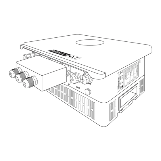
Page 13: Electrical Connections
11. Electrical Connections Install with a suitably rated circuit breaker All wiring must be carried out by a suitably qualified technician. Item Port Name Description Technical Features PV1+ ≤20A 1st PV Panel Positive Input Port PV1- 1st PV Panel Negative Input Port ≤20A 2nd PV Panel Positive Input Port PV2 +... - Page 14 Symbol Name Technical Specifications for single phase 230V input R/L, S, AC INPUT Terminals R/L, S and T/N for 3 phase 415V input Power Input and Motor Output ground terminal Ground Terminal The 3-phase pump motor connects to the U/V/W U,V,W AC OUTPUT Terminals output terminals respectively.
-
Page 15: Flexi Solar Installation
12. FLEXI-SOLAR installation FLEXI-SOLAR has an IP65 rating but avoid installing the controller exposed to direct sunlight or weather. Installing under the solar panels will provide protection. Ambient temperature should be maintained in the range 0- 45 deg C and humidity between 20 to 90%. At higher temperatures the output of the controller will be de-rated When installing and moving, please hold the bottom of the product, not just the casing, to prevent injury or damage to... - Page 16 Low Level Float Switch Wiring (Optional) DI2 / GND In order to avoid damage to the pump caused by dry running, a source water level float can be connected to the DI2 & GND terminals of the Flexi-Solar. Ensure the float delivers a closed signal to DI2 and GND terminals when water level is too low.
-
Page 17: Display Introduction
13. Display Introduction Using the display screen, the controller can be stopped or started its working status can be monitored. Programming is achieved using an external keypad. Controller programming cannot be accessed via the main display To Start or Stop, Short Press to scroll and Press and Hold for 3 sec view display parameters... - Page 18 13a. Display Introduction con’t Icon Name Function Controller State The colour and behaviours of the outer ring provides a clear Indicator indication of the Controller Status Solar Array This icon displays in the 10 o’clock position when there is a Indicator DC power input Input Power...
-
Page 19: Controller Programming
14. Controller Programming Programming should only be carried out by suitably trained personnel. Parameters randomly modified or altered in error can induce abnormal operation and have the potential to harm the controller as well as the water supply system, or even to cause personal injury or accidents. -
Page 20: Power On And Commissioning
14a. Controller Programming con’t Example: Setting the rated motor power in Parameter Group 2, address F2.01 If the controller is behaving in an unusual manner, it is highly possible that a parameter has been altered in error. In this event, navigate through each Group and every Parameter, resetting to factory default values. - Page 21 Press the START/STOP button to start the motor briefly and slowly to check whether the rotation of it is correct. If the pump is in a dry running state, the maximum running time should not exceed 15s, otherwise the pump mechanical seal may be damaged. If the direction is wrong, turn off the DC switch, then swap any two of the 3 cables connecting the motor and controller U/V/W ports.
-
Page 22: Programming Groups And Parameter Details/Defaults
16. Programming Groups and Parameter Details/Defaults Parameter can be altered whether the is controller stopped or running. Controller must be stopped to change parameter. Measured value a manufacturer's default which cannot be changed. Basic Parameters (31 parameters total – 20 related to Flexi-Solar pumping operation) Comms Address Name... - Page 23 Comms Address Name Setting Range Default Remarks Address Running 0: Standby (Sleep) F0.15 Mode at 1: Running at F0.14 0x00F F0.14 2: Stop Carrier 8.0 as maximum for Model F0.16 0.5 ~ 15.0kHz 0x010 Frequency Dependent SVC mode Acceleration Model F0.18 0.0 ~ 6500.0s 0x012...
- Page 24 Comms Address Name Setting Range Default Remarks Address Motor Varies Leakage 0.1 - 6500.0mH 0x20B F2.10 according Inductance to the Motor Controller 0.1 - 6500.0mH 0x20B Mutual F2.11 Model Inductance Option 1 for the motors which can be totally removed 0:No Option from their load Motor...
- Page 25 Alarm and Protection Comms Address Name Setting Range Default Remarks Address Motor overload FA.00 20 – 250% 0xA00 warning factor Motor overload FA.01 20.0 - 250% 100% 0xA01 protection factor Fault Self FA.02 recovery 0.1 – 100.0sec 30.0 sec 0xA02 interval Over voltage FA.03...
- Page 26 Comms Address Name Setting Range Default Remarks Address Host and 0:Host Auxiliary FD.03 Setting in 1:1st Auxiliary 0xD02 Multi Drive 2:2nd Auxiliary System Screen off FD.04 0 min – 1000 min (16.7 hrs) 30 min 0 = Never off 0xD03 delay MPPT 0:Keypad Setting...
- Page 27 Comms Address Name Setting Range Default Remarks Address Lower Limit FD.18 of MPPT 250.0V to setting at FD19 500.0V 0xD11 Voltage Upper Limit FD.19 of MPPT Setting FD18 to 800.0V 600V 0xD12 Voltage Lower Limit FD.20 of MPPT 0.0% to setting at FD21 0xD13 Frequency Upper Limit...
- Page 28 Latest Error Record (12 parameters) Error E0.00 0xE000 Codes 0 :No Error 1 :Reserved 2 :Overcurrent during acceleration (E02) 3 :Overcurrent during deceleration (E03) 4 :Overcurrent at constant speed (E04) 5 :Overvoltage during acceleration (E05) 6 :Overvoltage during deceleration (E06) 7 :Overvoltage at constant speed (E07) 8 :Snubber resistor overload (E08) 9 :Low input voltage (E09)
-
Page 29: Controller Error Codes
Reserved group – DO NOT ALTER (12 parameters) Reserved group – DO NOT ALTER (12 parameters) 17. Controller Error Codes Even in bad weather conditions, nXt Flexi Solar will try to drive the water pump to lift water. To ensure reliable service life, system components must be protected from factors that can damage equipment. - Page 30 17a. Controller Error Codes con’t Code Description Possible Cause Solution Reduce load and check motor and Load is too great, or the motor is jamming mechanical condition Controller overload Select the controller that matches the motor Controller model is too small power and load conditions The motor overload protection parameters (FA.01-FA.02) are not properly...
- Page 31 17b. Controller Error Codes con’t Abnormal current detection circuit Seek technical support Current detection failure Control board failure Seek technical support Motor tuning Motor parameters. F2 parameters are not Set motor parameters according to the failure set according to the nameplate nameplate Parameter R/W Control board failure...
-
Page 32: Maintenance
18. Maintenance Periodic Maintenance Operation can suffer if the controller suffers over-heating. Ambient temperature should be maintained in the range 0-40 deg C and humidity between 20 to 90%. Over the life of the controller, a build-up of dust or dirt can result in the controller operating at a higher temperature than normal. -
Page 33: Trouble Shooting Guide
19. Trouble Shooting Guide The nXt Flexi-Solar controller continuously monitors the performance of the system and can detect various abnormal conditions. In many cases, the controller will provide compensation as needed to maintain uninterrupted running of the system. If there is a possibility of equipment damage, the controller will protect the system and display the fault status;... -
Page 34: Warranties - Terms And Conditions
20. Warranties – Terms and Conditions This warranty is given in addition to the consumer guarantees found within the Australian Competition and Consumer Act 2010 (Cth) for goods purchased in Australia and the Consumer Guarantees Act 1993 NZ for goods purchased in New Zealand: 1) White International Pty Ltd / White International NZ Ltd (White International) warrant that all products distributed are free from defects in workmanship and materials, for their provided warranty period as indicated on the top or opposite side of this document. - Page 35 www.whiteint.com.au www.whiteint.co.nz Please always refer to our website for further technical information & new product innovations Disclaimer: Every effort has been made to publish the correct information in this manual. No responsibility will be taken for errors, omissions or changes in product specifications. ©...
Need help?
Do you have a question about the NXT FlexiSolar22 and is the answer not in the manual?
Questions and answers