
Related Manuals for THORLABS LFE1220W

Summary of Contents for THORLABS LFE1220W
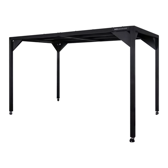
- Page 1 LFE1220W Optical Table Enclosure LFE1220W Optical Table Enclosure Installation Manual Original Instructions...
-
Page 3: Table Of Contents
LFE1220W Optical Table Enclosure Table of Contents Introduction ........................1 Chapter 1 Safety ..........................2 Chapter 2 2.1. General Warnings and Cautions ................2 Installation ........................3 Chapter 3 3.1. Installation Requirements ..................3 3.2. Environmental Conditions ..................3 3.3. Parts List ........................4 3.4. -
Page 4: Chapter 1 Introduction
Monitor (AQM) or other devices can be added according to requirements. The LFE1220W is intended to be used as a wrap around enclosure for 1.2 m x 2.0 m (4’ x 6’) Nexus optical tables and includes a walkway space between the optical table and the enclosure frame. -
Page 5: Chapter 2 Safety
LFE1220W Optical Table Enclosure Chapter 2: Safety Chapter 2 Safety For the continuing safety of the operators of this equipment, and the protection of the equipment itself, the operator should take note of the Warnings, Cautions and Notes throughout this handbook and, where visible, on the product itself. -
Page 6: Chapter 3 Installation
LFE1220W Optical Table Enclosure Chapter 3: Installation Chapter 3 Installation 3.1. Installation Requirements The Laminar Flow Enclosure is designed to be installed around an optical table. Warning Due to the weight and dimensions of the components, the following procedure must be performed by at least two persons. -
Page 7: Parts List
LFE1220W Optical Table Enclosure Chapter 3: Installation 3.3. Parts List Note The various supports and uprights look very similar to each other and some differ only in the placement of attachment holes. The different parts can be identified by colored stickers on the packaging as indicated in the table below. - Page 8 LFE1220W Optical Table Enclosure Chapter 3: Installation Enclosure Frame Continued… Code Description Image Corner Gusset RH Corner Gusset LH Roof Panel – Inner Roof Panel – Outer Roof Panel – Central XE25S2 Slot Cover Profile Rev A August 2021 Page 5...
- Page 9 LFE1220W Optical Table Enclosure Chapter 3: Installation Accessories Box Code Description Image M6 Square Nut M6 Washer M6 x 1.0 Low Profile Channel Screw, 16 mm Long M6 x 1.0 Hammerhead Screw, 12.7mm Long (XE25HM6) M6 Nut Assembly Block Barrel Plug...
-
Page 10: Installing The Roof Frame Assembly
LFE1220W Optical Table Enclosure Chapter 3: Installation 3.4. Installing the Roof Frame Assembly 3.4.1. Required Parts: Code Description Longitudinal Filter Support Outer Lateral Filter Support Long Top Cross Member Central Lateral Filter Support M6 Square Nut M6 Washer M6 x 1.0 Low Profile Screw, 16 mm Long... - Page 11 LFE1220W Optical Table Enclosure Chapter 3: Installation The construction rails are assembled by sliding the head of low profile screws into the T-slots of the construction rail. To enable the assembly, the spacing between the end of the construction rail and the underside of the screw head must be set to a specific distance.
- Page 12 LFE1220W Optical Table Enclosure Chapter 3: Installation Fit the end of Longitudinal Filter Support RH (A ) into the T-slot recesses of the Lateral Filter Support (C and slide across approx. 12.5mm [0.5"] to align the screws with the through holes.
- Page 13 LFE1220W Optical Table Enclosure Chapter 3: Installation Repeat steps 1 to 5 to produce a second inner frame sub assembly with Longitudinal Supports attached to a Lateral Support. Figure 6 Assembly of Longitudinal and Lateral Filter Supports – Step 6...
-
Page 14: Roof Frame Assembly
LFE1220W Optical Table Enclosure Chapter 3: Installation 3.4.3. Roof Frame Assembly Take one of the inner frame sub-assemblies from step 6, and insert an assembly block (AF) under each of the Longitudinal Supports to lift them 25 mm as shown below, so that the whole of the assembly sits horizontally. Take the ... - Page 15 LFE1220W Optical Table Enclosure Chapter 3: Installation Insert eight M6 Square Nuts (AA) into the Central Lateral Filter Support (E ); two into the top and middle slot of each end, on the side with the angle brackets in contact. Slide these nuts down until they are in position behind the angle bracket (the T-handle hex driver can be used to position the nuts in place behind the angle bracket slot).
- Page 16 LFE1220W Optical Table Enclosure Chapter 3: Installation Ensure that the longitudinal supports are correctly positioned against the alignment bars, then use four M6 Washers (AB) and four M6 x 16 Low Profile Screws (AC) to screw into the square nuts inserted in step 8 to fix the bracket to the central lateral support, making sure that the top surfaces are flush.
- Page 17 LFE1220W Optical Table Enclosure Chapter 3: Installation 10. Repeat steps 7 to 9 to attach the remaining sub assembly from step 6 to the other side of the central lateral support member, forming an inner roof frame. Figure 10 Roof Frame Assembly – Step 10 11.
- Page 18 ) to the inner frame assembled in the previous steps as shown below. (note that the inner frame fits to the face WITHOUT the Thorlabs name plate). Insert the screw heads on the lateral supports into T-slot recesses and slide along approx. 12.5mm to align screw heads with access holes.
- Page 19 LFE1220W Optical Table Enclosure Chapter 3: Installation 13. It is recommended that 2 people perform this step. Fit the assembly blocks (AF) underneath the Long Top Cross Member (D ) as shown below, to lift it by 50mm and make it easier to access the lower 2 screws. Using the T-handle hex driver supplied, tighten the lower 2 screws for each of the 3 lateral supports.
- Page 20 LFE1220W Optical Table Enclosure Chapter 3: Installation 14. It is recommended that 2 people perform this step. Repeat steps 12 and 13 to attach the remaining Long Top Cross Member (D Figure 14 Roof Frame Assembly – Step 14...
- Page 21 LFE1220W Optical Table Enclosure Chapter 3: Installation 15. using the Assembly blocks as shown below, set the spacing of the low profile screws (as per step 2) in both ends of the 2x Long Top Cross Members (D Figure 15 Roof Frame Assembly – Step 15 The completed Roof Assembly is used in the next section.
-
Page 22: Inner Roof Panel Fitting
LFE1220W Optical Table Enclosure Chapter 3: Installation 3.5. Inner Roof Panel Fitting 3.5.1. Required Parts: Code Description Roof Panel - Inner Push Rivet Barrel Plug Large Roof Panel 3.5.2. Roof Panel Fitting 16. Peel back the protective plastic film from both faces of Inner Roof Panels (K) by about 50 mm (2 in.) so that the fixing holes can be accessed. - Page 23 LFE1220W Optical Table Enclosure Chapter 3: Installation 17. Lay the 4x Inner Roof Panels (K) and Central Panel (M) onto the roof frame assembly (from step 15). Note that the panels have 1 glossy and 1 matt side. The panels can be assembled with either finish on the inside of the frame;...
- Page 24 LFE1220W Optical Table Enclosure Chapter 3: Installation Note The push rivets have 2 parts: the lower part (1) inserts into the hole and then the top part (2) is pushed in which expands the rivet and locks it in place. In order to ensure that the panel is aligned properly before being fixed, place the push rivets into all the holes in a panel before securing by pushing the top down.
- Page 25 LFE1220W Optical Table Enclosure Chapter 3: Installation 19. Insert qty 10x Barrel plugs (AG) into the corresponding holes on the outer edge of the inner panels. Figure 19 Inserting the Barrel Plugs 20. Put the finished Roof Frame Assembly to one side.
-
Page 26: Upright Frame Assembly
LFE1220W Optical Table Enclosure Chapter 3: Installation 3.6. Upright Frame Assembly 3.6.1. Required Parts: Code Description Short Top Cross Member G Frame Upright RH Frame Upright LH Corner Gusset RH Corner Gusset LH M6 Washer Hammer Head Screw... - Page 27 LFE1220W Optical Table Enclosure Chapter 3: Installation 22. It is recommended that 2 people perform this step. Lay the parts flat on the floor. Take a Frame Upright RH (G ) and a Frame Upright LH (H ). Ensure the parts are oriented such that the ...
- Page 28 LFE1220W Optical Table Enclosure Chapter 3: Installation 23. It is recommended that 2 people perform this step. Use the assembly blocks (AF) as shown below to raise the ends of the frame uprights by 50 mm. Using the T-handle driver supplied, tighten the assembly screws on ...
- Page 29 LFE1220W Optical Table Enclosure Chapter 3: Installation 24. It is recommended that 2 people perform this step. Repeat step 22 and 23 to create a second set of uprights. Figure 23 Two Upright Assemblies Page 26 ETN057352-D02...
-
Page 30: Fitting The Roof Frame Assembly
LFE1220W Optical Table Enclosure Chapter 3: Installation 3.6.3. Fitting the Roof Frame Assembly 25. It is recommended that 4 people perform this step. Lift up one end of the roof frame completed in step 20, supporting each end, so that the frame is at an angle. Hold in this position. - Page 31 LFE1220W Optical Table Enclosure Chapter 3: Installation 27. It is recommended that 4 people perform this step. Slide the assembly screws into the slots of the frame uprights – they will align with the central and outer slot as shown. Slide down until seated against the positioning screws.
- Page 32 LFE1220W Optical Table Enclosure Chapter 3: Installation 28. It is recommended that 4 people perform this step. Lift the other side of the roof frame assembly so the top of the frame is horizontal, supporting at the two free ends of the long top cross members. Use steps as necessary to lift the frame to this height.
- Page 33 LFE1220W Optical Table Enclosure Chapter 3: Installation 29. It is recommended that 4 people perform this step. Take the remaining set of uprights completed in step 24. Stand them up on their castors, vertically, with the position screws facing the open ends of the roof frame.
- Page 34 LFE1220W Optical Table Enclosure Chapter 3: Installation 30. It is recommended that 4 people perform this step. Position the uprights below the ends of the long top cross members. Lift the ends slightly, align the slots, and slide the assembly screws down into the slots until seated on the positioning screw.
- Page 35 LFE1220W Optical Table Enclosure Chapter 3: Installation 31. Check that all the screws are tight, and the legs are square to the roof frame. There should be no gaps. 32. Prepare four Corner Gusset RH (I) and four Corner Gusset LH (J) by pre-installing the fasteners. Each Gusset requires five M6 Washers (AB), five Hammer Head Screws (AD), and five M6 Nuts (AE).
- Page 36 LFE1220W Optical Table Enclosure Chapter 3: Installation 33. Fit the gussets from step 32 to the frame as shown below. Align the heads of the hammerhead screws with the slots in the extrusion then push the heads inside. Once inside the slot, turn the screws clockwise such that the slot on the end of the hammerhead screw is perpendicular to the slot in the extrusion as shown below, use a screwdriver as necessary.
- Page 37 LFE1220W Optical Table Enclosure Chapter 3: Installation 34. Using the same process as in steps 17 and 18, attach the outer roof panels (L) to the frame using push rivets (AH). Position the panels as shown below, with the corner cutouts aligned with the slots in the extrusion and the circular cutout aligned with the cutouts on the inner panels.
- Page 38 LFE1220W Optical Table Enclosure Chapter 3: Installation 35. Using the same process as in step 19, insert qty 6 Barrel Plugs (AG) into the corresponding holes. Figure 33 Fitting the Barrel Plugs Rev A August 2021 Page 35...
- Page 39 LFE1220W Optical Table Enclosure Chapter 3: Installation 36. If required, fit qty 16 barrel plugs to the underside of the holes. Figure 34 Fitting the Barrel Plugs to the Underside Page 36 ETN057352-D02...
-
Page 40: Using The Slot Cover Profile
LFE1220W Optical Table Enclosure Chapter 3: Installation 3.7. Using the Slot Cover Profile The slot cover profile (K) is supplied for use as a dust cover, panel holder, or to route cables in the slots in the extrusion. When inserted with the flat side facing out, the extruded plastic profile covers the T-slot in the frame, preventing dust and dirt build up for clean applications. -
Page 41: Removing Push Rivets
LFE1220W Optical Table Enclosure Chapter 3: Installation 3.8. Removing Push Rivets This can be done by lifting the head of the rivet with a flat head screw driver or similar tool. Page 38 ETN057352-D02... -
Page 42: Chapter 4 Specifications
LFE1220W Optical Table Enclosure Chapter 4: Specifications Chapter 4 Specifications General Specifications 1, 2, 3 Maximum Load on Roof (For Storage) 210 kg 1, 2, 3 Maximum Load per Construction Rail 100 kg Total Weight 140 kg Foot Height Adjustment... -
Page 43: Chapter 5 Thorlabs Worldwide Contacts
Contact Thorlabs for more information. Waste treatment is your own responsibility. “End of life” units must be returned to Thorlabs or handed to a company specializing in waste recovery. Do not dispose of the unit in a litter bin or at a public waste disposal site. - Page 44 www.thorlabs.com...
Need help?
Do you have a question about the LFE1220W and is the answer not in the manual?
Questions and answers