Table of Contents
Advertisement
Quick Links
Heatcraft
Smart Controller
H-IM-80F
July 2017
Part No. 25000601
Replaces H-IM-80E (06-17)
Installation and
Operation Manual
Table of Contents
Features . . . . . . . . . . . . . . . . . . . . . . . . 2-3
Installation Tips . . . . . . . . . . . . . . . . . . . . . 4
Wiring . . . . . . . . . . . . . . . . . . . . . . . . . . . . 5
Power Supply . . . . . . . . . . . . . . . . . . . . . . 6
Initialization of Smart Controller . . . . . . . . 7
Button Functions . . . . . . . . . . . . . . . . . . . . 7
Programming Smart Controller . . . . . . . . . 8
Monitoring Smart Controller . . . . . . . . . . . 9
Locking Smart Controller . . . . . . . . . . . . 10
Error Codes . . . . . . . . . . . . . . . . . . . . . . . 10
Wiring Error . . . . . . . . . . . . . . . . . . . . . . 11
Alarm Codes . . . . . . . . . . . . . . . . . . . . . . 11
Alarm Buzzer . . . . . . . . . . . . . . . . . . . . . 12
Data Logging . . . . . . . . . . . . . . . . . . . . . 12
Smart Defrost . . . . . . . . . . . . . . . . . . . . . 13
System Defaults . . . . . . . . . . . . . . . . . . . 14
Back Compatibility . . . . . . . . . . . . . . . . . 15
Wiring Diagrams . . . . . . . . . . . . . . . . 16-23
Advertisement
Table of Contents

Related Manuals for Heatcraft H-IM-80F


Summary of Contents for Heatcraft H-IM-80F
-
Page 1: Table Of Contents
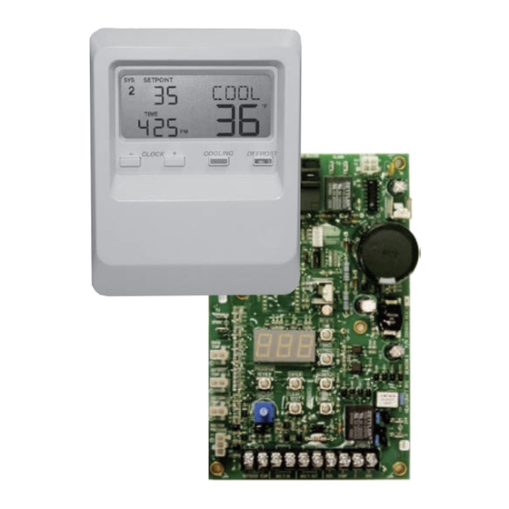
Heatcraft Smart Controller H-IM-80F July 2017 Part No. 25000601 Replaces H-IM-80E (06-17) Installation and Operation Manual Table of Contents Features ......2-3 Installation Tips . - Page 2 Heatcraft Smart Controller Features The Smart Controller performs all the standard Beacon II and Smart Controller allows complete monitoring and QRC functions with the additional benefit of: programming of the system. The Controller display has the following buttons: COOLING, Remote mounting for easy access DEFROST, PROG REVIEW, MONITOR, ENTER, CLEAR, SETPOINT AND TIME.
-
Page 3: Features
Heatcraft Smart Controller Features Features of the Smart Controller • • Monitoring of the complete refrigeration system. Each Smart Controller can control four independent systems with up to 4 evaporators on each system or 2 • systems with 8 evaporator boards. -
Page 4: Installation Tips
Installation Tips Installation The Smart Controller should be installed in a location where A terminal strip for wiring connections is located on the base of the large Liquid Crystal Display (LCD) can be viewed easily, yet the Smart Controller. To access this terminal strip, pull both halves is secure and vibration free. -
Page 5: Wiring
Wiring Wiring For MULTIPLE Independent Refrigeration All 24 volt wiring must be run separate from the line voltage wiring. Systems: All low voltage wiring must be 18 gauge minimum and must be run separate from high voltage wiring. The maximum distance from the For the first system, connect MULTI OUT 1 from the Smart Smart Controller to the master evaporator is 1000 ft. -
Page 6: Power Supply
Power Supply Power Supply The Smart Controller 24 V power should come from one of two sources: When the RS-232 port on the Smart Controller is NOT used: When the RS-232 port on the Smart Controller IS connected to a device: •... -
Page 7: Initialization Of Smart Controller
Initialization of Smart Controller Initialization of Smart Controller • When power is first applied to the Smart Controller, it checks the COOLING: Depressing this button will start the system in configuration of the system to which it is connected and stores the cooling cycle immediately (The 4 minutes “Hold Off”... -
Page 8: Programming Smart Controller
Programming Smart Controller Programming Smart Controller • To make a change, press the PROGRAM REVIEW button until the - Defrost Start time: Up to 12 settings per day (For DEF ST setpoint item that needs to be changed is displayed. The SETPOINT dF 1, use the “TIME”... -
Page 9: Monitoring Smart Controller
Monitoring Smart Controller • – Actual outdoor ambient temperature (Measured at OD TMP Programming Smart Controller cont'd. the Condensing Unit) • – ON or OFF: When placed in the ON mode this will SERVIC • – Evaporator coil temperature (Used to terminate DEFTMP pump the system down and shut it off. -
Page 10: Locking Smart Controller
Locking Smart Controller Locking The Heatcraft Smart Controller Error Codes Board • - Room temperature sensor shorted, BXSEN SMART CONTROLLER is lockable to prevent programmed settings open or not installed changes by unauthorized personnel. When the Smart Controller is Locked, all buttons except for the MONITOR, PROGRAM REVIEW, •... -
Page 11: Wiring Error
Wiring Errors & Alarm Codes Wiring Error The alarm code will flash alternately with the normal display If the Smart Controller LCD displays “ ,” this indicates information. When the alarm condition is corrected, the alarm code +COMM+ that there is an error in the communication wiring or that the will no longer be displayed and only the normal information will be wiring is broken or disconnected. -
Page 12: Alarm Buzzer
Alarm Buzzer and Data Logging Alarm Buzzer Data Logging On multiple evaporator systems, the data recorded is from the The ALARM buzzer will sound when an alarm condition occurs. This master evaporator only. This data is available via remote connection buzzer will turn off when the alarm condition is cleared. -
Page 13: Smart Defrost
Smart Defrost Smart Defrost Demand Defrost The Smart Controller continuously monitors the system performance to determine the need for defrost. It uses a variety of data such as the outdoor ambient and box temperature in it’s decision making Demand defrost is available for electric defrost systems only. To process. -
Page 14: System Defaults
System Defaults System Defaults The following are factory defaults for the parameters for the Smart Controller. If the user does not select a setting for any of the following parameters, the default will be used. It is important the user set ALL parameters based on their needs. PARAMETERS CODE ELECTRIC... -
Page 15: Back Compatibility
Back Compatibility In order to accomodate updates in technology and in industry, new Beacon II, QRC, and Smart Controller part numbers were created to handle a number of enhancements. The "NEW" part numbers listed below will serve as service parts for any "OLD" part numbers in the event a replacement part is needed. The Table and notes below highlight key differences between the OLD and NEW parts. -
Page 16: Wiring Diagrams
3. ALARM CONNECTION GOES TO A DRY CONTACT THAT CLOSES UPON LOSS OF POWER OR WHEN AN ALARM IS ACTIVATED (125 VAC, 1 AMP CONTACT). HEATCRAFT PART NO. 29661601 24 VOLT CONNECTION WIRING W/ SINGLE SYSTEM CONNECTION DIAGRAM FOR SMART CONTROLLER II... - Page 17 2. CAN BE CONNECTED TO (1) BEACON II BOARD AT THE EVAPORATOR (TERMINALS 24V & C). 3. ALARM CONNECTION GOES TO A DRY CONTACT THAT CLOSES UPON LOSS OF POWER OR WHEN AN ALARM IS ACTIVATED (125 VAC, 1 AMP CONTACT). HEATCRAFT PART NO. 29661901 MULTI #1 MULTI #2 REV C...
- Page 18 2. CAN BE CONNECTED TO (1) BEACON II BOARD AT THE EVAPORATOR (TERMINALS 24V & C). 3. ALARM CONNECTION GOES TO A DRY CONTACT THAT CLOSES UPON LOSS OF POWER OR WHEN AN ALARM IS ACTIVATED (125 VAC, 1 AMP CONTACT). HEATCRAFT PART NO. 29682101 MULTI #1 MULTI #2 REV B...
- Page 19 2. CAN BE CONNECTED TO (1) BEACON II BOARD AT THE EVAPORATOR (TERMINALS 24V & C). 3. ALARM CONNECTION GOES TO A DRY CONTACT THAT CLOSES UPON LOSS OF POWER OR (125 VAC, 1 AMP CONTACT). WHEN AN ALARM IS ACTIVATED HEATCRAFT PART NO. 29664201 MULTI #1 MULTI #2 REV C...
- Page 20 Quick Response Controller Wiring Diagrams 24 VOLT CONNECTION WIRING W/ SINGLE SYSTEM CONNECTION DIAGRAM FOR SMART CONTROLLER II CONNECTION DIAGRAM FOR SMART CONTROLLER II (WITH ONE EVAPORATOR) (WITH ONE EVAPORATOR) SMART CONTROLLER II EVAPORATOR MULTI OD TEMP MULTI 18 GA MULTI IN FIELD WIRING...
- Page 21 Quick Response Controller Wiring Diagrams 24 VOLT CONNECTION WIRING W/ 2 SYSTEMS CONNECTION DIAGRAM FOR SMART CONTROLLER II (TWO SEPARATE SYSTEMS / (1) EVAPORATOR ON EACH SYSTEM) SYSTEM 1 SYSTEM 2 EVAPORATOR EVAPORATOR OD TEMP OD TEMP MULTI IN MULTI IN MULTI OUT MULTI OUT 18 GA...
- Page 22 Quick Response Controller Wiring Diagrams 24 VOLT CONNECTION WIRING W/ 4 SYSTEMS CONNECTION DIAGRAM FOR SMART CONTROLLER II CONNECTION DIAGRAM FOR SMART CONTROLLER II (FOUR SEPARATE SYSTEMS / (2) EVAPORATOR ON EACH SYSTEM) (FOUR SEPARATE SYSTEMS / (1) EVAPORATOR ON EACH SYSTEM) SYSTEM 2 SYSTEM 4 EVAPORATOR TB...
- Page 23 Quick Response Controller Wiring Diagrams 24 VOLT CONNECTION WIRING W/ 4 SYSTEMS 24 VOLT CONNECTION WIRING W/ 4 SYSTEMS CONNECTION DIAGRAM FOR SMART CONTROLLER II CONNECTION DIAGRAM FOR SMART CONTROLLER II (FOUR SEPARATE SYSTEMS / (2) EVAPORATOR ON EACH SYSTEM) (FOUR SEPARATE SYSTEMS / (2) EVAPORATOR ON EACH SYSTEM) SYSTEM 2 SYSTEM 4...
- Page 24 Heatcraft Refrigeration Products, LLC 2175 West Park Place Blvd., Stone Mountain, GA 30087 www.heatcraftrpd.com Customer Service and Technical Support Normal Business Hours – 8:00 AM – 8:00 PM EDT (800) 321-1881 After Hours (after 5:00 PM EDT, weekends and holidays)
Need help?
Do you have a question about the H-IM-80F and is the answer not in the manual?
Questions and answers