Table of Contents
Advertisement
______________________________________________________________________________
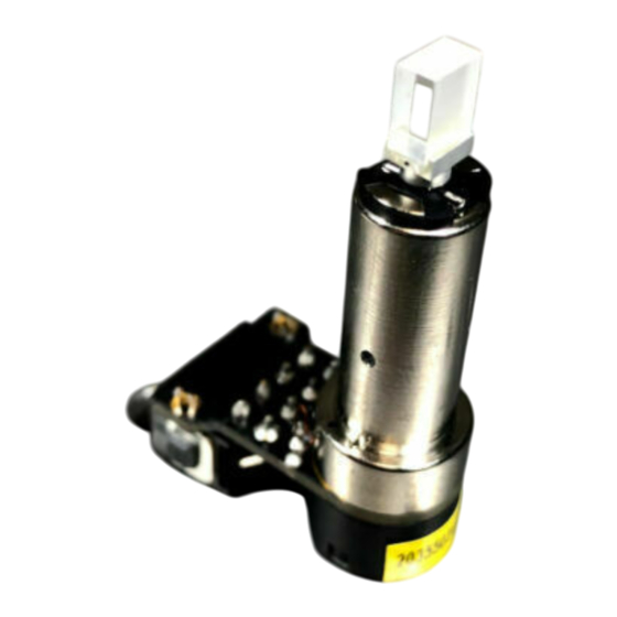
Model 6210H
Galvanometer Optical Scanner
INSTRUCTION MANUAL
CAMBRIDGE TECHNOLOGY, INC.
109 Smith Place
Cambridge, MA 02138
U.S.A.
TEL.617-441-0600 FAX.617-497-8800
www.cambridgetechnology.com
Revision 1, September 22, 2004
Advertisement
Table of Contents

Related Manuals for Cambridge Technology 6210H

Summary of Contents for Cambridge Technology 6210H
- Page 1 ______________________________________________________________________________ Model 6210H Galvanometer Optical Scanner INSTRUCTION MANUAL CAMBRIDGE TECHNOLOGY, INC. 109 Smith Place Cambridge, MA 02138 U.S.A. TEL.617-441-0600 FAX.617-497-8800 www.cambridgetechnology.com Revision 1, September 22, 2004...
-
Page 2: Table Of Contents
Cambridge Technology Model 6210H Instruction Manual TABLE OF CONTENTS 1.0 Introduction and Warnings _______________________________________________3 2.0 Specification ____________________________________________________________4 3.0 Description of Operation__________________________________________________6 3.1 Overview _____________________________________________________________6 3.2 Mounting Scheme ______________________________________________________7 3.3 Mirrors_______________________________________________________________9 3.3.1 Mirror Replacement Kit_____________________________________________9 3.3.2 Replacement Mirror Removal Procedure_______________________________9 3.3.3 Replacement Mirror Mounting Procedure_____________________________10 3.3.4. -
Page 3: Introduction And Warnings
Cambridge Technology Model 6210H Instruction Manual 1.0 Introduction and Warnings This manual was written to help the customer use the Model 6210H scanner successfully. There are several warnings and precautions written throughout this manual. Read this manual carefully. It is possible to damage the scanner by exposing it to rough handling or contaminants. -
Page 4: Specification
Cambridge Technology Model 6210H Instruction Manual 2.0 Specification Note: All angles are in mechanical degree unless stated otherwise. Scanner MODEL NO. 6210H Tolerance Units/Notes Mechanical Specifications ±20 Rated Excursion, Rotor degrees ±26 ±4 Bumper Stop Angle, Initial Contact degrees Optical Aperture, Two-Axis, Std. - Page 5 Notes: 1. 6210HM40 is reduced to ±10° excursion and ±14° initial contact. 2. Setup for settling time: Using CTI’s recommended servo, CTI’s 3mm Y-mirror, moving a 0.1° step, and settled to within 99% of the final position. 3. Using the Cambridge Technology, Inc. Position Demodulator circuit.
-
Page 6: Description Of Operation
CTI driver electronics. The 6210H is now available in a variety of connector versions so that the smallest scanner in the world is now one of the most flexible to integrate. The standard 6210H comes with the standard or “straight”... -
Page 7: Mounting Scheme
To calculate the necessary heatsinking for the 6210H, there are two approaches. 1. Worst case analysis: This assumes that there are two scanners bolted to a common heatsink and both are dissipating their full power. - Page 8 If any part of this procedure is not completely understood, contact CTI for technical assistance. For the 6210H scanner, the only valid mounting surface is the long cylindrical section of the body. See the Outline Drawing in Section 5.1 at the end of this manual. The scanner must be mounted by this surface to adequately transfer the heat out.
-
Page 9: Mirrors
Model 6210H Instruction Manual Mirrors The 6210H is designed to have the mirror glued directly into a slot in the end of the output shaft. This minimizes the extra inertia required to hold the mirror in a removable mount. The standard slot width is shown in the outline drawing in Section 5.1. -
Page 10: Replacement Mirror Mounting Procedure
The Mirror Replacement Kit contains a two-part stainless steel fixture. The larger piece, referred to as the Alignment Tool, slips over the drive housing of the 6210H. The Alignment Tool has a semi- circular window for viewing the mirror installation and curing processes. The smaller piece, the Plunger, has ends that are machined for the two different mirror widths. -
Page 11: The 6210Hs Solid Shaft Motor
Model 6210H Instruction Manual the 6210H output shaft, just enough to fill the slot. As the 6210H mirrors are of very small mass, only a very small amount of epoxy is necessary. Refer to D04733 to see how much epoxy is required and for the proper orientation. -
Page 12: Cabling
Model 6210H Instruction Manual Cabling The Model 6210H and 6210HR motors have been optimized to be as small as possible but still use a connector. The 6210H employs a small, straight 8-pin Amp connector. The 6210HR uses a right angle version of this connector. The standard cables for both are:... -
Page 13: Attaching The Cable To The Motor
This procedure should be used when the cable end to be attached to the motor has been properly prepared. The cable is properly prepared when it leaves Cambridge Technology, but if the cable length needs to be modified, or if a wire is damaged during assembly, refer to Section 3.4.2, Modifying the Cable Length, shown below. -
Page 14: Modifying The Cable Length
Cambridge Technology Model 6210H Instruction Manual 4.) Cut off any excess wire that protrudes from the far side of the soldered hole to minimize the possibility of shorting. **Caution: Do not attempt to clean the flux off of the solder connections. The cleaner may enter the scanner and contaminate it. - Page 15 Cambridge Technology Model 6210H Instruction Manual 6.) Heat the 1/16” piece of tubing at this time. Use caution not to overheat the insulation on the wires. 7.) Strip 1/8” of insulation from the other four conductors of this cable and the two conductors of the other cable.
-
Page 16: The 6210Hm
Cambridge Technology Model 6210H Instruction Manual The 6210HM For situations that require reduced angles, a different bumper design is employed which limits the rotation angle of the front stop pin of the scanner. These –M version scanners use a two-digit suffix which denotes the intended use angle in peak-to-peak optical degrees. -
Page 17: Limited Warranty
Model 6210H Instruction Manual 4.0 Limited Warranty The 6210H scanner is warranted to be free of defects in materials and workmanship for one year from the date of shipment. Cambridge Technology, Inc. will repair or replace, at our option, any part of the system which upon our examination is found to be defective while under warranty. -
Page 18: Appendix
Cambridge Technology Model 6210H Instruction Manual 5.0 Appendix Schematics and Mechanical Drawings The following drawings are included in this section: 1. Series 6000 Position Demodulator Components D01747 2. 6210H Outline Drawing D05833 3. 6210HL Outline Drawing D05978 4. 6210HR Outline Drawing Contact CTI 5.
Need help?
Do you have a question about the 6210H and is the answer not in the manual?
Questions and answers