
Summary of Contents for potenza CM1-2
- Page 1 THE POWER OF TOMORROW. TODAY. Potenza LV Distribution Grid Inverter (DGI) Customer Manual CM1-2...
- Page 2 PLEASE READ ALL INSTRUCTIONS CAREFULLY BEFORE USE KEEP SAFE FOR FUTURE REFERENCE The contents of this Customer Manual are subject to recurring updates and modifications, as the Potenza LV DGI undergoes regular reviews for improvements. Before any use, please check and download the latest revision of the Customer Manual using the QR code below to stay informed about any future changes.
- Page 3 (including anything that would create independent economic significance) without the express written permission of TPS. CM1-2 Revision 1 The information contained in this document is to be considered proprietary information. It shall not be reproduced, disclosed, or used without the prior written permission of Turbo Power Systems Ltd.
-
Page 4: Table Of Contents
4.8.2. Internal Termination Details ........................19 4.8.3. Connection of 3P 415VAC Cables and PE to the Potenza LV DGI ............. 19 4.8.4. Connection of the DC supply cables out of the Potenza LV DGI DC Interface Unit ..... 20 4.8.5. Connection of Communications ......................... 20 5. -
Page 5: General Information
Before contacting TPS, please ensure you have the serial number of your Potenza LV DGI to hand. Details of where to find the serial number are in section 3.5.1 of this manual. The serial number must be quoted in all communications with TPS. -
Page 6: Acronyms And Abbreviations
Vehicle to Grid Vehicle to Everything 1.4. Figures It is not always possible or practical to show the exact configuration of your Potenza LV DGI. Any figures used within this document are indicative and are for instruction and description purposes only. -
Page 7: Safety
NOTE readily apparent from the text or illustrations. CM1-2 Revision 1 The information contained in this document is to be considered proprietary information. It shall not be reproduced, disclosed, or used without the prior written permission of Turbo Power Systems Ltd. -
Page 8: Safety Precautions To Consider When Working On The Equipment
The DGI should always be installed to allow access and good ventilation, especially to the rear of the unit. • Do not place any objects which could block the vents. See Appendix A Potenza LV DGI - OUTLINE of this manual for required clearances for ventilation and access. •... -
Page 9: Disclaimer
The manufacturer (Turbo Power Systems) is not liable for any damages, losses, costs, expenses, or injuries incurred by any USER of the Potenza LV DGI, if such damages, losses, costs, expenses, or injuries occur as a result of failure to comply with all the instructions contained in this manual. This includes but is not limited to the following: •... -
Page 10: Product Information
Electrical Safety, and To IEC 61000-6-4, IEC 61000-6-2, IEC 61000-3-12 for EMC. As illustrated in Figure 1, a TPS Potenza LV Distribution Grid Inverter (DGI) connects to the 415 VAC grid supply. This module converts the AC grid supply to a regulated 800 VDC bus. The DGI will constantly monitor and maintain this 800 VDC nominal level enabling the establishment of a DC micro grid. -
Page 11: Technical Overview
Near silent operation Where grid capacity is sufficient, a Potenza LV DGI can be used with one or more of TPS own Velox i EVCs to provide a ‘hub and spoke’ EV charging system, with V2G/V2X capability. Where grid capacity is insufficient, energy storage and on-site generation can be added to optimise charging site operational costs. -
Page 12: General Arrangement Of Potenza Lv Dgi
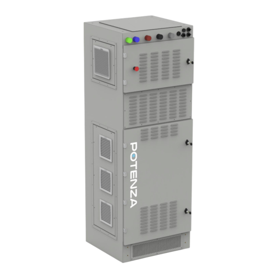
3.4. General Arrangement of Potenza LV DGI Rating plate can be found here Figure 2 - Potenza LV DGI 3.5. General Arrangement of Potenza LV DGI with optional DC Interface Unit Figure 3 - Potenza LV DGI with integrated DC Interface Unit CM1-2 Revision 1... -
Page 13: Rating Plate
Longer Term Storage If the Potenza LV DGI is switched off for a period exceeding 6 months, an inspection will be needed before it can be switched back on. This must be carried out by TPS or an approved / trained person. -
Page 14: Installation
Installation PLEASE NOTE: The Potenza LV DGI and any combinations must only be installed by Turbo Power Systems or a qualified Installation Engineer. The qualified Installation Engineer must: • Have a full working knowledge of the DGI and any DGI combinations, and their safe installation. -
Page 15: Lifting And Positioning The Potenza Lv Dgi (Stand Alone, No Combinations)
2. Fix the DGI directly to the concrete foundation using suitable fixings. 3. Align the DGI, tightening all fixings to recommended torques. See Appendix A Potenza LV DGI - OUTLINE for the latest information relating the installation. CM1-2 Revision 1... -
Page 16: Unpacking The Potenza Lv Dgi And Integrated Dc Interface Unit
4.5. Unpacking the Potenza LV DGI and integrated DC Interface Unit Before attempting to unpack the Potenza LV DGI and integrated DC Interface Unit, perform a check of the transport indicators. There are 2 types of indicators fitted; one to record shock, the other to record tilt. -
Page 17: Electrical Installation Of The Potenza Lv Dgi (Stand Alone No Combinations)
It can be found here: Appendix A Potenza LV DGI - OUTLINE. The Potenza LV DGI electrical supply must be delivered via a suitable, lockable isolation box supplied by the Owner. -
Page 18: Connection Of 3P 415Vac Cables And Pe To The Potenza Lv Dgi
4.7.3. Connection of 3P 415VAC Cables and PE to the Potenza LV DGI Figure 5 - DGI Power and Communication inputs The connectors used for the 3P 415VAC inputs are manufactured by Phase 3 Connectors and are of the ‘Powersafe type’, 500 Amp rating. A 5mm allen key driver will be required. Torque fixings to 10.5 Information on how to terminate the connectors can be found here:- https://www.distributionzone.com/getattachment/b15efbd0-d570-4a8c-bd12-... -
Page 19: Internal Termination Details
All power cables must be cut to a suitable length and terminated in an approved manner using the correct tooling. Use the following information as a guide, and reference to the suggested fixing torques. 4.8.3. Connection of 3P 415VAC Cables and PE to the Potenza LV DGI Follow the instructions in section 4.7.3 CM1-2 Revision 1... -
Page 20: Connection Of The Dc Supply Cables Out Of The Potenza Lv Dgi Dc Interface Unit
Depending upon specification, there may be a requirement to connect an ethernet communications and a Can-Bus cable to the Potenza LV DGI. These should be connected to the connection points shown above in Figure 5 - DGI Power and Communication inputs. Refer to specific installation drawing for details of cable types. -
Page 21: Commissioning And Operation
5.1. Potenza LV DGI Operation The stand alone Potenza LV DGI is simple to operate. It is switched on by energising the main isolator for the 3P 415V incoming supply after first ensuring that the internal MCB’s are not tripped and the E Stops are unlocked. -
Page 22: Preventative Maintenance And Inspection Information
Figure 8 - DC Isolators Preventative Maintenance and Inspection Information PLEASE NOTE: the Potenza LV DGI contains no USER serviceable components. All repairs and maintenance can only be carried out by either Turbo Power Systems or an approved / trained representative. -
Page 23: Cleaning The Exterior Of The Potenza Lv Dgi
6.1. Cleaning the Exterior of the Potenza LV DGI When cleaning the exterior, do not use high pressure water jets (pressure washer or steam cleaner) as there is a risk water can leak into the interior and cause serious damage to internal components and / or potentially electrocution to persons. -
Page 24: Enclosure And Doors
DGI Status LED Figure 9 - DGI Status LED location CM1-2 Revision 1 The information contained in this document is to be considered proprietary information. It shall not be reproduced, disclosed, or used without the prior written permission of Turbo Power Systems Ltd. -
Page 25: Hmi (If Fitted)
Locate the HMI. If fitted it will be in the lower door of the DC Interface Unit. Ensure the display is working, it will be displaying the status of the DGI. CM1-2 Revision 1 The information contained in this document is to be considered proprietary information. It shall not be reproduced, disclosed, or used without the prior written permission of Turbo Power Systems Ltd. -
Page 26: Trouble Shooting
• For more information, contact the Government Waste-Disposal department in your country. CM1-2 Revision 1 The information contained in this document is to be considered proprietary information. It shall not be reproduced, disclosed, or used without the prior written permission of Turbo Power Systems Ltd. -
Page 27: Document History
Changed by number 12/07/2024 New document A Lister CM1-2 Revision 1 The information contained in this document is to be considered proprietary information. It shall not be reproduced, disclosed, or used without the prior written permission of Turbo Power Systems Ltd. -
Page 28: Appendix A Potenza Lv Dgi - Outline
Appendix A Potenza LV DGI - OUTLINE Indicative information only. Dimensions may be subject to change. Latest version can be found here: CM1-2 Revision 1 The information contained in this document is to be considered proprietary information. It shall not be reproduced, disclosed, or used without the prior written permission of Turbo Power Systems Ltd. -
Page 29: Appendix B Installation Checklist Document
Have you unpacked the Potenza LV DGI as set out in section Error! Reference source not found. / 4.6? Have you lifted the Potenza LV DGI in location as set out in section 5 / 4.7? Have you mechanically installed the Potenza LV DGI as set out in section Error! Reference source not found.? -
Page 30: Appendix C Maintenance & Inspection Record
Link to the latest version:- Interval Equipment Part No. / Description Type of Inspection Ref No. (Months) Cleaning the Exterior of the Visual and clean Potenza LV DGI Air Ducts Visual / clean as required Enclosure and Doors Visual Visual Visual CM1-2 Revision 1 The information contained in this document is to be considered proprietary information. - Page 31 Appendix D – Packing Link to the latest version:- CM1-2 Revision 1 The information contained in this document is to be considered proprietary information. It shall not be reproduced, disclosed, or used without the prior written permission of Turbo Power Systems Ltd.
- Page 32 This page is intentionally left blank. CM1-2 Revision 1 The information contained in this document is to be considered proprietary information. It shall not be reproduced, disclosed, or used without the prior written permission of Turbo Power Systems Ltd.
Need help?
Do you have a question about the CM1-2 and is the answer not in the manual?
Questions and answers