Table of Contents
Advertisement
Quick Links
DEALER
USER MANUAL
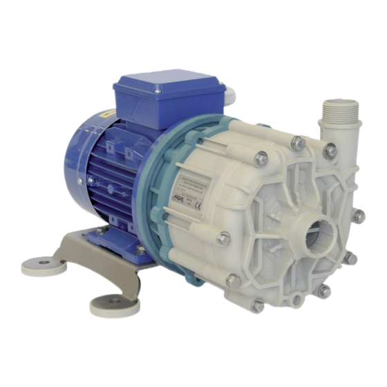
TMR G2 (sealless)
For maintenance:
date of commissioning
References: position/system reference
Service:
.......................................................................................
.......................................................................................
.......................................................................................
Advertisement
Table of Contents

Related Manuals for Argal Route TMR G2 Series


Summary of Contents for Argal Route TMR G2 Series
- Page 1 USER MANUAL TMR G2 (sealless) DEALER For maintenance: date of commissioning ..................References: position/system reference ..................Service: ..................
- Page 2 INDEX 3 IDENTIFICATION CODE 4 DISASSEMBLING SEQUENCE 5 HYDRAULIC PARTS LEGEND 6 ‘MOTOR PARTS LEGEND 7 GENERAL NOTES 8 OPERATING PRINCIPLE 8 MOTOR 9 DRY RUNNING SURVEY 9 INSTRUCTIONS ON INSTALLATION AND USE 9 STORAGE INSTRUCTIONS 9 TRANSPORT 9 INSTALLATION 10 START-UP 11 USE 11 SHUTDOWN...
-
Page 3: Identification Code
IDENTIFICATION CODE Pump data Motor data range model execution (materials) internal structure power phase □ 06.10 □ WR □ 1450 □ 0.18 kW □ 1 □ R1 (polipropilene PP) (C/Al (monofase) □ 10.10 □ GF □ 2900 □ 0.25 kW □... -
Page 4: Disassembling Sequence
DISASSEMBLING SEQUENCE TOOLS Spanner No 13 EXECUTION NOTES • To facilitate the pump disassembling operations, first disassembly the HYDRAULIC PARTS from the MOTOR PARTS • unscrew the connections (POS.1) • warning! The disassembly operations of parts magnetically connected involve great opposed forces: keep the MO- TOR PARTS fixed on floor during the removing of the HYDRAULIC PARTS. -
Page 5: Hydraulic Parts Legend
HYDRAULIC PARTS LEGEND EXECUTION NOTES • disassembly keeping the pump in vertical position (suction on top) TOOLS • unscrew the connections (POS.2) Spanner No 10 Fig. 2.1 A – disassembling sequence HYDRAULIC PARTS Spare stock for Disassembling steps sequence working years note pos. -
Page 6: Motor Parts Legend
MOTOR PARTS LEGEND TOOLS • Screw driver • Type Phillipsq • punch f < 4 mm NOTE OPERATIVE • Unscrew the connections (POS.10) • Remove the collar from the drive magnet assembly using the punch (see paragraph 9.1) Fig. 2.2 A – disassembling sequence MOTOR PARTS Spare stock for Disassembling steps sequence working years... -
Page 7: General Notes
GENERAL NOTES “TRM” pumps are designed and built for the transfer of liquid chemical products having a specific weight, viscosity, temperature and stability of state appropriate for use with centrifugal pumps in a fixed installation, from a tank at a lower level to a tank or a pipe to a higher level. -
Page 8: Operating Principle
The electrical connection to the motor terminal determines the direction of rotation of the motor and can be verified by looking at the cooling fan at the rear of the motor ( for the Argal pump this has to rotate clockwise looking at the front end). -
Page 9: Dry Running Survey
DRY RUNNING SURVEY Though the pump can run dry (execution R1-R2) , it is therefore suitable to safeguard the pump and the plant to use: • pressure switch; • fluxmeter; • control devices for the motor power absorbtion. INSTRUCTIONS ON INSTALLATION AND USE TRANSPORT •... - Page 10 0.00 • anchor the pump to an adequate base plate having a mass at least 5 times that of the pump • do not use anti-vibration mounts to fix the pump • anti-vibration joints are recommended on the pipe connections •...
-
Page 11: Maintenance
• switch automatic control on • do not activate valves whilst the pump is in operation • risks of dangerous water hammer effects in case of sudden or improper valve actuation (only trained personnel should operate valves) • completely empty and wash the pump before using a different liquid •... - Page 12 tion to avoid damage. • As described on paragraph no. 2 “Disassembling sequence”, unscrew the connections (POS.1) and remove the HYDRAULIC PARTS from the MOTOR PARTS • Proceed separately to disassembly the HYDRAULIC PARTS or the MO- TOR PARTS following the sequence described on paragraph no. 2 “ Fig.
- Page 13 ASSEMBLY Tools required: size 10-13 socket spanner, screw driver (Phillips drive type) Bolts have right-hand thread Bolt torque setting: (reduce by 25% on plastic parts) Nm 4 Fig. 9.3 A • all these maintenance operations must be performed under supervision of qualified personnel •...
-
Page 14: Safety Risks
SAFETY RISKS WARNING! MAGNETIC FIELDS. Magnetic pumps contain some of the most powerful magnets in existence. The magnets are positioned on the back of the impeller and the outer magnet housing. The magnetic fields may adversely affect persons fitted with electronic devices (e.g. pacemakers and defibrillators): such persons must not be allowed to handle magnetic pumps and magnetic pump com- ponents. -
Page 15: Waste Disposal
PERSONNEL RESPONSIBLE FOR REPAIRS Interventions allowed to general operators under the supervision of qualified personnel: • stopping of the pump • closing of the valve • emptying of pump body • disconnection of piping from fittings • removal of anchoring bolts •... -
Page 16: Operating Faults And Possible Causes
OPERATING FAULTS AND POSSIBLE CAUSES Pump does not deliver: rotates in wrong direction suction pipe is excessively long and tortuous insufficient geodetic pump head or excessive suction geodetic lift 4.air infiltration into the suction pipe or branches 5.pump or suction pipe not completely covered by liquid 6.impeller channels blocked by impurities check valve on discharge pipe jammed geodetic system height is greater than maximum potential pump head... -
Page 17: Technical Data
TECHNICAL DATA d x z d x z model 06.10 10.10 10.15 16.15 16.20 02.30 model 07.11 07.14 11.15 11.23 17.25 03.35 (1) can change for motors of different brands dimension in mm... - Page 18 model 14.94 8.44 4.875 5.44 07.11 16.94 5.875 6.34 0.375 7.28 9.75 9.66 12.13 15.94 8.125 07.14 16.94 18.5 9.375 6.625 7.125 0.41 8.06 10.2 14.13 16.94 8.125 5.875 6.34 0.375 7.28 9.75 9.66 12.13 11.15 18.5 9.375 19.5 9.625 2.65 2.94 5.125...
- Page 19 POSITIONING DRIVE MAGNET ASSEMBLY H = 20 mm H = 10 mm H = 0 mm IEC 71 IEC 80 IEC 90 H = 5.65 mm H = 2.4 mm H = 3.5 mm IEC 100-112 NEMA 56 NEMA 143-145 (#): internal Ø...
-
Page 20: General Conditions Of Sale
Within twelve months from the time of installation and no more than eighteen months from delivery Argal undertakes to examine any defective parts and to promptly replace any faulty parts free of charge if it is responsible for the fault. Such faults must not be due... - Page 21 Even machines that are under warranty must be sent to Argal carriage paid. Once the machines have been repaired they will be returned to the purchaser carriage forward. The replaced parts remain the property of Argal and must be returned to Argal.
-
Page 22: Warranty Form
Place for sketch of the installation ARGAL S.R.L. – Via Labirinto, 159 – 25125 BRESCIA (ITALY) – Tel. +390303507011 Fax. +3903003507077 Mail: pec@pec.argal.it - P. IVA/ VAT 00583130174 – Joint Stock € 51.480,00 I.V. - R.E.A. 203878 – Co. registration 11615... -
Page 24: Manufacturer Data
Rev. 25 - 09/20 The INSTRUCTION MANUAL must be delivered to the pump-user , who © Copyright 2020 - ARGAL srl takes diligent note of it, fills in data for Maintenance Department (page Draw and text total or partial duplication is 1), keeps the file for subsequent reference.Possible modifications do not...
Need help?
Do you have a question about the Route TMR G2 Series and is the answer not in the manual?
Questions and answers