Advertisement
Available languages
Available languages
Quick Links
SAVE THESE INSTRUCTIONS – This manual contains IMPORTANT SAFETY
INSTRUCTIONS that should be followed during installation and maintenance of the UPS and
batteries.
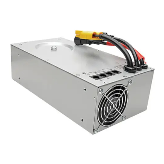
The HC150 and HCINT150 series of hospital cart power modules are designed to provide AC voltage output
power from either utility provided AC input voltage or from inverting DC power from a battery. The HC150SL,
HC150LVR, and HCINT150SL may be configured for either a Lithium Iron Phosphate (Li-Ion) battery or a sealed
lead acid (SLA) battery (not provided). The HCINT150L model works only with a Li-Ion battery. To ensure proper
operation, the following guidelines should be observed:
General:
1. The power module can support continuous AC loads up to a maximum of 150VA or 150W.
2. The HC150SL and HC150LVR models require 60Hz utility input. The HCINT150SL and HCINT150L models
automatically select the last utility frequency encountered (50Hz or 60Hz) for invert mode operation.
3. The appliance inlet dongle serves as a disconnect device and shall be easily accessible.
4. Alternately, the socket-outlet of the end-product shall be installed near the equipment and shall be easily
accessible or disconnect device provided within the end product.
5. A Remote User Interface (RUI) module (not provided) must be connected to the power module using two
CAT-5 cables (not provided, 5 ft./1.5 m max length). The COMM1 jacks should be connected together and
the COMM2 jacks should be connected together. If the cables are not connected or if they are interchanged,
the power module will not operate. The RUI may be either a Tripp Lite RUI or a customer designed RUI that
meets Tripp Lite specifications.
6. The power module is able to provide many operational parameters to monitoring software (such as Tripp
Lite's PowerAlert) running on a computer that has a USB connection to the power module (a 2 ft./0.6 m USB
cable is provided).
7. The rated temperature range for the fan inlet air to the power module is 0°C to 40°C.
8. The power module has internal over temperature protection. If the internal temperature becomes greater than
85°C, the power module will shut down (no VAC output and no charging). If the temperature drops below
85°C, charging will resume but the VAC output will remain off until the On switch on the RUI is pressed.
9. When using a Li-Ion battery, a communication cable (not provided, 5 ft./1.5 m max length) is required from the
power module COMM3 connector to the battery communication connector. This allows the battery to
communicate its operating parameters to the power module, including state of charge and over temperature
conditions (the power module will interrupt current into or out of a battery if a battery reports an internal
temperature alarm exceeding about 60°C). Caution: To prevent possible damage to the power module, make
battery DC power connections before making communication connections (and reverse the procedure when
disconnecting the battery).
10. When using SLA batteries with HC150SL, HC150LVR, or HCINT150SL models, a communication cable is not
used. To provide added fault protection for SLA batteries, the HC150SL and HCINT150SL models may be
equipped with optional temperature sensors (Tripp Lite P/N AC8441) connected from their THERM1 and/or
THERM2 connectors to the negative terminals of the batteries. The sensors need to be enabled by
reprogramming the power module using a software tool available from Tripp Lite. The sensors allow the
power module to interrupt current into or out of a battery if a battery temperature exceeds 50°C. If a sensor
has been enabled, a missing or open sensor will also cause a shut down.
11. CAUTION: Double Pole/Neutral Fusing.
24-08-034 933217_RevE
HC150 and HCINT150 Series Application Guidelines
Series AGSM7328, AGSM7892
Tripp Lite is now part of Eaton.
1000 Eaton Boulevard
Cleveland, OH 44122
United States
TrippLite.Eaton.com
Advertisement

Subscribe to Our Youtube Channel
Related Manuals for Tripp Lite HC150 Series


Summary of Contents for Tripp Lite HC150 Series
- Page 1 COMM2 jacks should be connected together. If the cables are not connected or if they are interchanged, the power module will not operate. The RUI may be either a Tripp Lite RUI or a customer designed RUI that meets Tripp Lite specifications.
-
Page 2: Installation
12A maximum current. The power module will provide an appropriate charging current (9.9A to 20A) for 33AH to 66AH SLA batteries when programmed with the software tool available from Tripp Lite. If the internal temperature of the power module reaches 65°C while charging at 20A, it will fold back the charging current to 16A to prevent overheating (charging at 16A or less reduces internal temperatures). - Page 3 6. The DC power cable to the battery must be tightly secured to the battery terminals using the torque recommended by the battery manufacturer. Caution: Loose DC power connections may cause over temperature issues for the battery, the wiring, or the power module. 7.
- Page 4 APPENDIX - EMC Technical Description Standard Description Test Level/Limit Emissions Radiated Emissions Class A Group 1, 55011:2016+A1:2017+A2:2021+A11:2020 30 - 1000 MHz Conducted Emissions Class A Group 1, 55011:2016+A1:2017+A2:2021+A11:2020 150 kHz – 30 MHz Immunity EN 61000-4-2 :2009 Electrostatic Discharge ±2, ±4, ±8, ±15 kV Air Immunity Discharge ±8 kV Contact...
- Page 5 6. El módulo de potencia es capaz de proporcionar muchos parámetros operativos al software de monitoreo (como PowerAlert de Tripp Lite) que se ejecuta en una computadora que tenga una conexión USB con el módulo de potencia (se suministra un cable USB de 0.6 m/2 pies).
-
Page 6: Instalación
AH. Consulte con Tripp Lite para confirmar que la batería prevista está caracterizada para su uso con el módulo de potencia. 2. Los modelos HC150SL, HCINT150L y HCINT150SL se envían programados para su uso con una batería de iones de litio. - Page 7 externos, ya que el funcionamiento seguro está garantizado por fusibles internos no sustituibles. No obstante, si el cliente desea evitar que los fusibles internos se fundan en caso de una sobrecarga extrema, deberá instalar un fusible externo o breaker de circuito con una tensión nominal de 6 A en la entrada de tensión de CA.
- Page 8 APÉNDICE - Descripción técnica del EMC Estándar Descripción Nivel / Límite de Prueba Emisiones Emisiones Radiadas Grupo 1 Clase A, 55011:2016+A1:2017+A2:2021+A11:2020 30 - 1000 MHz Emisiones Conducidas Grupo 1 Clase A, 55011:2016+A1:2017+A2:2021+A11:2020 150 kHz - 30 MHz Inmunidad EN 61000-4-2 :2009 Inmunidad a Descarga ±2, ±4, ±8, ±15 kV de Electrostática...
- Page 9 Wenn die Kabel nicht angeschlossen sind oder vertauscht werden, funktioniert das Leistungsmodul nicht. Bei der RUI kann es sich entweder um eine RUI von Tripp Lite oder um eine vom Kunden entwickelte RUI handeln, die den Spezifikationen von Tripp Lite entspricht.
- Page 10 Batterie mit einem maximalen Strom von 12A laden. Das Leistungsmodul liefert einen angemessenen Ladestrom (9,9A bis 20A) für 33AH bis 66AH SLA-Batterien, wenn es mit dem von Tripp Lite erhältlichen Softwaretool programmiert wird. Wenn die Innentemperatur des Leistungsmoduls beim Laden mit 20 A 65 °C erreicht, wird der Ladestrom auf 16 A reduziert, um eine Überhitzung zu vermeiden (das Laden mit 16 A oder...
- Page 11 4. Die AC Spannungseingangs- und -ausgangsverbindungen werden mit vom Benutzer gelieferten Kabeln an den IEC C14-Eingangsanschluss und den IEC C13-Ausgangsanschluss des Leistungsmoduls angeschlossen. Verwenden Sie nur zugelassene Stecker-/Kabelsätze entsprechend den elektrischen Nennwerten des Geräts. Die Kabellänge für den AC-Ausgang des HCINT150 darf 10 m nicht überschreiten. Eine externe Absicherung ist nicht erforderlich, da der sichere Betrieb durch interne, nicht austauschbare Sicherungen gewährleistet wird.
- Page 12 APPENDIX – EMC Technische Beschreibung Standard Beschreibung Teststufe/Beschränkung Emissionen: Strahlungsemissionen Klasse A Gruppe 1, 55011:2016+A1:2017+A2:2021+A11:2020 30 – 1000 MHz Leitungsgebundene Emissionen Klasse A Gruppe 1, 55011:2016+A1:2017+A2:2021+A11:2020 150 kHz – 30 MHz Immunität EN 61000-4-2:2009 Störfestigkeit gegen ±2, ±4, ±8, ±15 kV elektrostatische Entladungen Luftauslass ±8 kV Kontaktentlassung,...
Need help?
Do you have a question about the HC150 Series and is the answer not in the manual?
Questions and answers