Advertisement
Quick Links
Advertisement

Related Manuals for CISON L4-175


Summary of Contents for CISON L4-175
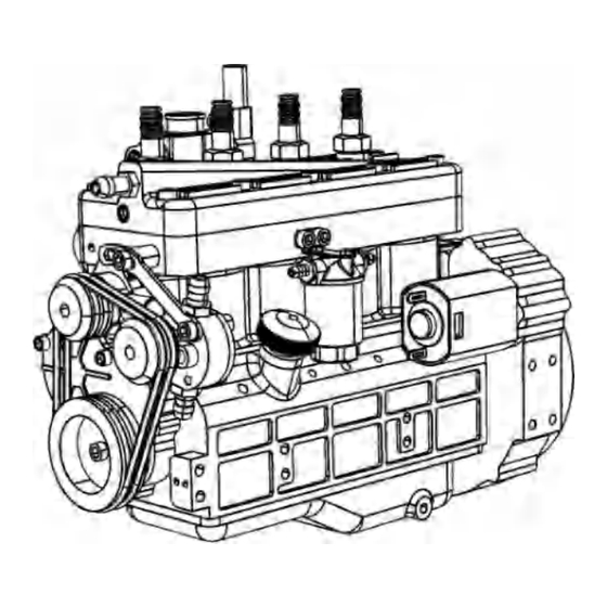
- Page 1 CISON CISON L4-175 Operation manual...
- Page 2 CISON ENGINES be careful: 1. Some parts may have been pre installed and may not exist in the parts box. 2. Some gaskets and sealing rings may be used for backup and do not necessarily need to be installed. 3. Please install in strict accordance with the installation requirements 4.
- Page 3 CISON ENGINES Part packaging distribution diagram (mixed diagram of flat head and OHV version, not all of which are actually displayed) 11(OHV版本)
- Page 4 CISON ENGINES Part packaging layout 41 42 47(OHV版本)...
- Page 5 CISON ENGINES Part packaging layout...
- Page 6 CISON ENGINES 46(4*1) 8(m3x2) 49(8*1) Make the throttle hole coincide Chute up, pushing 10(M2) When installing the air valve screw, it must be aligned with the chute to avoid Installation to avoid excessive force fracture crushing the throttle valve...
- Page 7 CISON ENGINES Product assembly steps 1. Please clean the cylinder again Inside the sleeve to prevent dust from scratching the piston 2. Install the cylinder liner back Note: the appearance should Take out the cylinder be moistened 50(Install 3 liner...
- Page 8 Use M2.5 screws in the red circle of part No. 9 (M2.5), Note that the screw is used to plug and adjust the oil volume to ensure that each oil outlet hole basically has the same oil volume. Test and regulate the flow before operation, Note: the oil filter element is purchased additionally 22(Oil pump...
- Page 9 CISON ENGINES Alignment The two m3 on 44(Set screw between two the side are moved to locating forbidden to be Keyway holes installed position, fixed Timing gear) 58(Crankshaft fulcrum bearing Crankshaft set screw) (0.1mm/Adjust support Note: after the gasket and...
- Page 10 CISON ENGINES 56(0.3mm) 38(Install the end bearing first, and then put the camshaft into the cylinder block) Note: This gasket shall be added according to the actual situation. If the clearance is appropriate, it may not be added...
- Page 11 CISON ENGINES 37(271/243 Anaerobic adhesive fixation) 11(Note: screws have been used instead of keyway pins to facilitate disassembly) shim 12(243 anaerobic adhesive fixation. When installing the inert gear Note: after , please add a 4x8x0.2 installation, gasket first) ensure that the...
- Page 12 Scheme 2: the use of a cast iron ring and a high- CISON ENGINES temperature and wear- resistant O-ring may lead Please add to higher engine lubricating oil to temperature and greater the piston surface torque. It is not and connecting rod...
- Page 13 CISON ENGINES 注意! The original pairing shall maintained during disassembly and shall not be confused . The concave point at the arrow shall also be kept correspondi ng during installation. Please install in the marked order...
- Page 14 CISON ENGINES Note: the bearing is divided into positive and negative, and the model mark corresponds to the gear small boss 11(243, 271 Note: when anaerobic installing the side cover, it must be shim Glue) installed as shown in the figure, with...
- Page 15 CISON ENGINES 42 43 (Optio (Opt ) 2 ) Scheme 2: the copper sleeve needs to be fixed and sealed with 243 anaerobic adhesive Recommendation: Option 1 Scheme 1: it is easy to install and disassemble without glue. M2.5(Note: this Scheme 2: there is a copper sleeve hole is M2.5)
- Page 16 CISON ENGINES The starting Note: please install the pinion before the big gear motor screw shall be put in before installing 41 14(SeeNotes) (screw No.: 1) (Before installation, please find the gasket with thickness of 0.2 in inner hole 3...
- Page 17 So we made a new patch. Add a deceleration to the starting motor. The original reduction ratio is 21 times, and the improved reduction ratio is about 33 times. Note that this is a free patch provided by cison, but we can't guarantee whether the dealer will charge your freight.
- Page 18 CISON ENGINES 25 Valve snap mounting structure Please install the valve in sequence. After installation, you can use a mobile phone flash to illuminate the air inlet to look for light in the dark. Check whether there is any foreign matter in...
- Page 19 CISON ENGINES Adjust to 10.2~ 10.25 suggestions (can be adjusted according to your own experience) intake: 10.25 exhaust: 10.2 243 anaerobic adhesive (warning, do not use high- strength screw adhesive)
- Page 20 CISON ENGINES No longer use locating pins Note: the oil 28、29 pump base has an installation direction...
- Page 21 CISON ENGINES 3*6*0.2 shim 36(243 anaerobic 3*5*4.5Plastic adhesive fixation) guide sleeve The pulley shim is fixed with high- strength 271 anaerobic adhesive. Fix the pulley note: the pulley groove should be flat with crankshaft pulley...
- Page 22 CISON ENGINES Note: water pump and oil pump pulley shall be adjusted before fixing with 271 anaerobic adhesive The sensor magnet mounting hole (the magnet is in the CDI package) and the mounting magnet must be flat...
- Page 23 CISON ENGINES 18+51(5x1 O-ring) Intake pipe exhaust pipe One or two shims Carburetor can be used to installation +49 adjust the (seal ring 10x2) compression Note: the gasket is ratio divided into positive and negative directions. Please pay attention to the position of this hole 47(5x1 O-ring...
- Page 24 CISON ENGINES After you receive the CDI igniter, there is a very small magnet in the package. Please note that there are colors on one side of the magnet , and those with colors are installed outward, as shown in the figure Just install a magnet in any mounting hole.
- Page 25 CISON ENGINES Hall installation position, as shown in the figure. Remove the two screws of the timing gear baffle, and then align the hall PCB board with the mounting hole Insert the high-voltage line according to the high-voltage line number on the CDI Magnet position: Rotate the flywheel.
Need help?
Do you have a question about the L4-175 and is the answer not in the manual?
Questions and answers