Advertisement
Quick Links
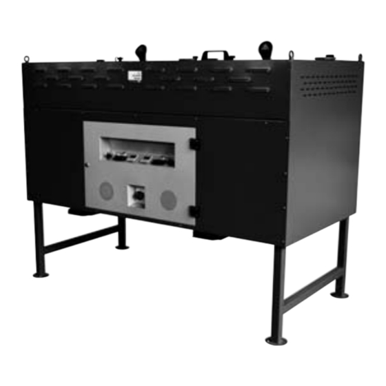
WELDRY FW100 / 200 / 400
GB
Hopper Drying Ovens for Fluxes
ISUM
Instructions for Safety Use and Maintenance
WELDRY FW 100: W 000 120 469
WELDRY FW 200: W 000 120 470
WELDRY FW 100: W 000 120 471
1. GENERAL INFORMATION
This instruction for safety, use and maintenance manual is an integral and essential part of the
product and is supplied together with the oven. It is suggested to read carefully this manual and
observe any stated indication in order to use the equipment correctly. Please take care of this
manual for any further consultation.
Typographic convention
Danger signal which indicates to
observe carefully the instructions
for avoiding possible damages to
the equipment or accident.
This manual wants to be an instructions and maintenance guide for Hopper Drying Ovens for
Fluxes WELDRY FW100 – FW200 - FW400, which are designed for WELDLINE - Air Liquide
Welding France: 13 rue d'Epluches - Saint Ouen l'Aumône - 95315 CERGY PONTOISE France
• It must be used and read by the operators, maintenance employees and by the staff and
purchaser for what it concerns spare parts.
• It must be located with care in a known place, protected by dirty and humidity and it
must be always available for consultation by the operators.
• Read it and give to read carefully to all the operators in all parts before proceeding to
install, to use, or for maintenance or dismantling of the oven and/or equipment.
• Check always that the operator has understood very well how to proceed for use and the
safety symbols fitted on the oven.
• Do not damage or remove the labels or the name-plate fitted on the oven.
• It is possible to prevent accidents if the given instructions are respected.
• Before connecting the oven be sure that the name-plate data correspond to the electrical
distribution system ones.
• Do not expose the oven to the inclemency of the weather or install in high humidity
environments, that is bathrooms, etc.
• In case of emergency, that is fire starting, anomalous noise, overheating, etc. disconnect
immediately the system electrical connection.
When this manual has been completely damaged, it is possible to ask for a copy directly to
WELDLINE at the above mentioned address giving the following references:
• Type of oven and Model
• Serial Number
• Supplier/Reseller
• Name and address of the User
• Correct address where to deliver the copy of the manual.
In case the oven is given to someone else, please inform us of the change in order to
communicate to the new owner the up-to-date information.
This manual respects the state of the art at the moment of sale and it could not be considered
inadequate if it is reviewed due to improvements.
The producer is not obliged to up-to-date the manual and/or the oven of the users if, in the
meantime, due to the evolution of the technology, he has modified and/or improved the
equipment and/or the manual.
2. SPECIFICATIONS
2.1. General specifications
The hopper ovens are mainly used for drying and keeping the welding fluxes used in submerged
arc welding.
Different models are available according to the load capacity and the temperature control
equipment. (see Table 1).
Table 1 – Available versions
Model
Description
WELDRY FW100 With nr. 1 hopper and 1 digital control panel
WELDRY FW200 With nr. 1 hopper and 1 digital control panel
WELDRY FW400 With nr. 2 hoppers and 2 digital control panels 7,9 kW
www.weldline-alw.com
N° 8695-8917
Creation date: 09/2008 - rev.0
Danger signal which indicated to
pay attention as hot surfaces are
present.
Load
Power
capacity
4 kW
60 kg
4 kW
160 kg
320 kg
2.2. Oven general description
The oven has an external structure made of sheet steel painted with epoxy powder coating to
withstand heavy working conditions as humidity, corrosion and salty atmosphere.
The inner hopperchamber is cone shaped, manufactured in stainless steel.
The flux is taken from the hopperchamber through a door located at the lower part of the hopper.
On the upper part of the oven there is a small door for loading the flux.
The main drive and the temperature control board are located in the front lower part of the oven.
2.3. Thermal insulation
Rock wool insulation is installed on the external structure of the hopper-chamber for a better
heat distribution throughout the oven chamber and a better thermal insulation. Insulation is
internally closed by a covering plate.
2.4. Heating elements
The spiral stainless steel heating elements are located into the hopper-chamber in direct contact
with flux. They can reach 800 °C (about 1500 °F) if left uncontrolled.
2.5. Weight and dimensions
External size (mm)
Internal size (mm)
Oven weight (kg)
Packaging size (mm)
Weight for transport (kg)
3. ASSEMBLING INSTRUCTIONS
The oven is packaged in heavy duty cardboard packaging for shipment. The oven is equipped
with eyebolts so that it can be handled by a lifting device.
Connect the oven electrical cable to the power supply in accordance with all local and national
electrical and safety standards. The working voltage and power rating are listed on a label
located on the oven.
Load the oven with the right flux quantity; the heating elements must be covered by the flux
during the drying cycle. The oven is now ready for use.
4. OPERATING INSTRUCTIONS
After checking the connections supply power to the oven, act on the general switch and the zone
selectors; the white pilot lights are now on.
After a self-control phase of 10 seconds, the thermo regulators are on and start doing the
ON/OFF symmetrical adjustment with 5°C hysteresis according to the temperatures and times
set up in advance.
IP Prot.Grade
SET POINT 1" (drying) 370 °C - 6 hours time
44
SET POINT 2" (keeping) 120 °C
with safety control on the heating elements at 470 °C.
44
Please note the oven is already pre-adjusted. The following instruction is useful only in
44
the case a different working temperature or time is required.
WELDRY FW100
WELDRY FW200
670 x 709 x 1300 825 x 819 x 1330
1620 x 850 x 1340
530 x 390 x 640 690 x 690 x 740 690 x 690 x 740 (each tank)
90
116
690 x 750 x 1320 850 x 860 x 1350
1640 x 870 x 1360
100
130
WELDRY FW400
210
225
Advertisement

Related Manuals for Air Liquide WELDLINE ISUM WELDRY FW 100

Summary of Contents for Air Liquide WELDLINE ISUM WELDRY FW 100
- Page 1 This manual wants to be an instructions and maintenance guide for Hopper Drying Ovens for 2.2. Oven general description Fluxes WELDRY FW100 – FW200 - FW400, which are designed for WELDLINE - Air Liquide Welding France: 13 rue d'Epluches - Saint Ouen l'Aumône - 95315 CERGY PONTOISE France The oven has an external structure made of sheet steel painted with epoxy powder coating to withstand heavy working conditions as humidity, corrosion and salty atmosphere.
- Page 2 WELDRY FW100 / 200 / 400 Hopper Drying Ovens for Fluxes 9.2. Separation of the components Complaints have to be sent directly to WELDLINE mentioning the reason of the defect. WELDLINE will give you further instructions for repairing or replacing the complained parts. The materials composing the drying ovens are: Any transport expenses will be covered by the customer.
Need help?
Do you have a question about the WELDLINE ISUM WELDRY FW 100 and is the answer not in the manual?
Questions and answers