Advertisement
Quick Links
PRECAUTIONS
• Read and understand all instructions before beginning installation.
• CAUTION: FOR USE WITH CLASS 2, LOW VOLTAGE SYSTEMS ONLY. DO NOT USE IN HIGH VOLTAGE APPLICATIONS. Low Voltage wiring is to be
isolated from line voltage wiring.
• NOTICE: For installation by a licensed electrician in accordance with National and/or local Electrical Codes and the following instructions.
• Confirm device ratings are suitable for application prior to installation. Use of device in applications beyond its specified ratings or in
applications other than its intended use may cause an unsafe condition and will void manufacturer's warranty.
• Use only approved materials and components (i.e. wire nuts, electrical box, etc.) as appropriate for installation.
• ALL EXCESS CABLE MUST BE REMOVED FROM WALL BOX PRIOR TO INSTALLATION. Connection between Cat5e/6 cable and switch connection
port must remain straight and true without interference or pressure from excess or misaligned cable.
• NOTICE: Do not install if product appears to be damaged.
SAVE THESE INSTRUCTIONS!
DESCRIPTION
The LVSRJ45 switch stations provide manual control for low voltage devices that require a momentary signal to actuate. For ease of installation on the
Hubbell Control Solutions LVSRJ45 switch stations provide manual control for low voltage devices that require a momentary signal to actuate. For
connection to the LVSRJ45 switch station there are two RJ45 ports located in the back of the wall station. The connections in the back of the station are
ease of installation on the connection to the LVSRJ45 switch station there are two RJ45 ports located in the back of the wall station. The connections
intended for daisy chain applications where the functionality is to be identical.
in the back of the station are intended for daisy chain applications where the functionality is to be identical.
SPECIFICATIONS
Electrical Ratings
Configurations
Operating environment
Construction
Dimensions
Weight
Mounting
Warranty
Note:
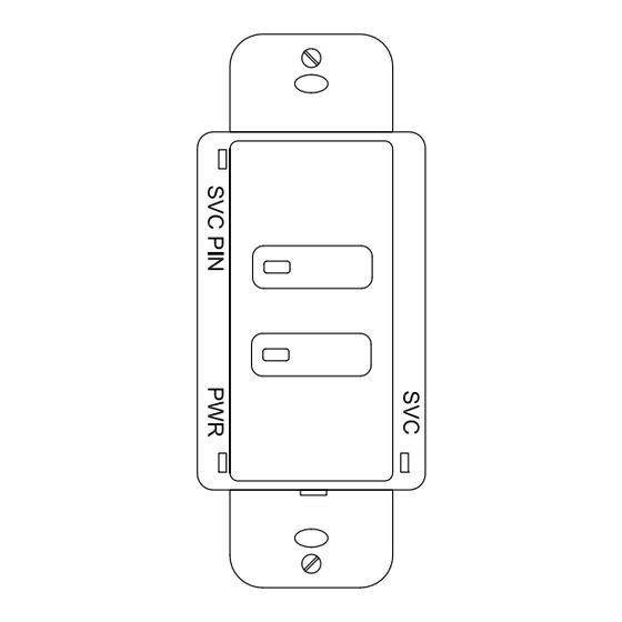
*Pilot Light functionality is not supported with UVPPM power packs Fig 5
LVSRJ45-2 Switch Station
(Front)
Copyright © 2018 Hubbell Control Solutions, a division of Hubbell Lighting, Inc. All rights reserved. All product and company names,
Each switch: 100mA @ 30VDC Max
Each pilot LED: 18-30VDC, internal 2.2kohm, ½ Watt resistor
2 and 3 buttons, with pilot LED Momentary
Indoor use only
Operating temperature: 32° to 122°F (0° to 50°C)
Relative humidity (non-condensing): 10%-90%
Housing – Rugged, high-impact, injection-molded plastic
2 - RJ45 ports on rear
1.88"W x 4.25"H x 1.56"D (47.75mm x 107.95mm x 39.63mm)
3.0 oz [85.0 g]
Single-gang NEMA-style switch box (average switch box)
Decorator-style wall plate not included
Five-year limited
LVSRJ45-3 Switch Station
(Front)
701 Millennium Blvd. | Greenville, SC 29607 | (864) 678-1000 | (866) 898-0131 - fax www.hubbellcontrolsolutions.com
currentlighting.com
logos and product identifiers are trademarks ™ or registered trademarks ® of Hubbell Lighting, Inc. or their respective owners.
Use of them does not necessarily imply any affiliation with or endorsement by such respective owners.
© 2022 HLI Solutions, Inc. All rights reserved. Information and specifications subject to change
without notice. All values are design or typical values when measured under laboratory conditions.
LVSRJ45 Switch
INSTALLATION GUIDE
LVSRJ45-x Switch Station
(Back)
72-00631
9700B 012918
LVSRJ45_Install-Guide_R01
Page 1 of 4
Rev 09/15/22
Advertisement

Related Manuals for Current LVSRJ45 Series

Summary of Contents for Current LVSRJ45 Series
- Page 1 LVSRJ45 Switch INSTALLATION GUIDE PRECAUTIONS • Read and understand all instructions before beginning installation. • CAUTION: FOR USE WITH CLASS 2, LOW VOLTAGE SYSTEMS ONLY. DO NOT USE IN HIGH VOLTAGE APPLICATIONS. Low Voltage wiring is to be isolated from line voltage wiring. •...
- Page 2 LVSRJ45 Switch INSTALLATION GUIDE T568B Scheme Number used to Wire Colors LVS Switch Define Pin-outs Functions RJ45 to LVSRJ45 To connect to low Switch Station Port voltage device input Figure 1 INSTALLATION Prepare the installation site as necessary, to install the switch. Using the diagrams per device type, connect the appropriate Cat5e/6 wiring using the T568B color coded configuration.
- Page 3 LVSRJ45 Switch INSTALLATION GUIDE PHx1PC LVSRJ45-3 Switch Station Figure 3 – Connections to PowerHUBB node Inputs LVSRJ45-3 Switch Station Figure 4 – Connections to NXDCIO Inputs 72-00631 701 Millennium Blvd. | Greenville, SC 29607 | (864) 678-1000 | (866) 898-0131 - fax www.hubbellcontrolsolutions.com Copyright ©...
- Page 4 LVSRJ45 Switch INSTALLATION GUIDE LVSRJ45-2 Switch Station Figure 5 72-00631 701 Millennium Blvd. | Greenville, SC 29607 | (864) 678-1000 | (866) 898-0131 - fax www.hubbellcontrolsolutions.com Copyright © 2018 Hubbell Control Solutions, a division of Hubbell Lighting, Inc. All rights reserved. All product and company names, currentlighting.com Page 4 of 4 logos and product identifiers are trademarks ™...
Need help?
Do you have a question about the LVSRJ45 Series and is the answer not in the manual?
Questions and answers