Table of Contents
Advertisement
Quick Links
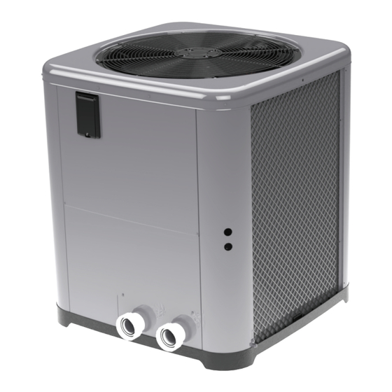
INSTALLATION & OPERATION MANUAL
Heat Pump Pool
& Spa Heater
MODELS: TWPH-6560 & 6560EHC
FOR YOUR SAFETY: Do not store or use gasoline or other flammable vapors and
liquids or other combustible materials in the vicinity of this or any other appliance.
To do so may result in an explosion or fire.
NOTE: The instructions in this manual are for the use of qualified individuals specially trained
and experienced in the installation and maintenance of this type of equipment and related system
components. Installation and service personnel are required by some states to be licensed. Persons
not qualified shall not attempt to install, service, or maintain this equipment.
This manual should be maintained in legible condition and kept adjacent to the heat pump pool heater or in a
safe place for future use.
Effective: 09-13-2024
Replaces: NEW
P/N: 100-10004031 Rev. 00
Advertisement
Table of Contents

Summary of Contents for WEATHERKING TWPH-6560
- Page 1 INSTALLATION & OPERATION MANUAL Heat Pump Pool & Spa Heater MODELS: TWPH-6560 & 6560EHC FOR YOUR SAFETY: Do not store or use gasoline or other flammable vapors and liquids or other combustible materials in the vicinity of this or any other appliance.
- Page 2 QUICK START GUIDE CLEARANCES POWER † Installation Considerations Page 6. † Electrical Connections Page 10. † Installation Clearances Page 7. † Table C. Typical System Electrical Power Requirements Page 10. † Hurricane Tie Down Instructions Page 8. PIPING CONTROLS INTERFACE †...
-
Page 3: Table Of Contents
TABLE OF CONTENTS 1. WARNINGS ............. 4 17. FREEZE PROTECTION ......... 27 Pay Attention to these Terms ........4 System Drain-Down ..........27 Continuous Pump Operation ......... 27 2. INTRODUCTION ............5 18. MAINTENANCE ............. 27 3. WATER CHEMISTRY ..........6 Air Coil Cleaning ........... -
Page 4: Warnings
1. WARNINGS Pay Attention to these Terms Indicates the presence of immediate hazards which will cause severe personal injury, death or substantial DANGER property damage if ignored. ndicates the presence of hazards or unsafe practices which could cause severe personal injury, death or WARNING substantial property damage if ignored. -
Page 5: Introduction
• Any service challenges present at the house/ 2. INTRODUCTION neighborhood: gated community, locked access at house, guard dog, etc. WARNING: This heat pump pool heater is an • Date of installation of the new unit electromechanical machine that incorporates pressurized refrigerant gas in a sealed system. -
Page 6: Water Chemistry
3. WATER CHEMISTRY Situate the heater carefully to minimize installation costs while providing maximum efficiency of operation, and to allow adequate service access, as follows: IMPORTANT: Damage from corrosive • For unrestricted air intake and service access, water is not covered under warranty. position each side of the unit at least 1 ft (30 cm) from walls, pipes and other obstructions. - Page 7 60" (1.52m) MIN AIR FLOW OUT 3 FT 12" (09.m) (0.3m) FLOW FLOW Figure 2. Installation Clearances 1. Install the WFS onto the water inlet piping as shown can be encountered, drain the water circuit to in Figure 47. prevent possible freeze-up damage. Refer to "Freeze Protection"...
- Page 8 Figure 5. Hurricane Tie Down Instructions...
-
Page 9: Water Connections
5. WATER CONNECTIONS CAUTION: The heater inlet and outlet are NOT interchangeable. They must be connected as instructed below. OUTLET INLET DRAIN PLUG 1. Connect the heater in the return water line between the filter and the pool/spa. See plumbing diagrams DRAIN PLUG on page 31 (without bypass) and page 32 (with bypass). -
Page 10: Electrical Connections
time clock overrides. Refer to the external control system’s 7. ELECTRICAL instructions, and "Remote Mode Selector", on page 24 CONNECTIONS of this manual, for installation information. An earth ground lug is located to the right-side of the water Refer to the unit rating plate below the control panel for connections. -
Page 11: Wiring Diagram
8. WIRING DIAGRAM 208V/230V Single-Phase INLET 100K GN/BK GN/BK COIL BK/RD BK/RD BK/RD BK/RD COMPONENT CODE SENSOR 10K DUAL SENSOR 100K PRESSURE SWITCH REVERSING VALVE (HEAT/COOL ONLY) CAPACITOR POWER RS-485 TEMPERATURE REMOTE GROUND 24VAC COMM SENSORS SELECTOR WATER PRESSURE MAIN SWITCH FUSE HIGH PRESSURE... -
Page 12: Heater Control Display
9. HEATER CONTROL 10. OPERATION MODES DISPLAY The user may select one of several operating modes. Each mode is selected by pressing the MENU button to The heater display is located in the front panel of the heat cycle between the modes. Each press of the MENU button pump, covered with a door. - Page 13 Timed Spa Mode Pool Cool Mode - Heat/Cool Models Only The control is equipped with a mode which will heat the In heat/cool models, the control is equipped with a "Pool spa to the Spa setpoint temperature for a specified period Cool Mode"...
-
Page 14: Service Menu
Example: When the POOL AUTO setpoint is set at 80°F NOTE: If you choose to set FACTORY DEFAULTS, the (27°C) and the cooling deadband set at 6°F (3.5°C), the pool and spa setpoints will return to their default values unit will automatically heat the pool if the temperature of 85°F (29°C) and 100°F (38°C), respectively, and the drops below 80°F (27°C), and will automatically cool the maximum temperature settings for pool and spa will be... - Page 15 Heat Pump Temperatures Press the MENU button again. The "HPPH Temp" screen indicates the water temperature sensed in the water inlet and at the heat pump coil of the heater. When the compressor is not running, the coil temp sensor reports ambient temperature.
-
Page 16: Operations And Service Menu
Operations and Service Menu OPERATION SERVICE MENU MODES OFF mode Press and hold 8:05PM MENU button for No Demand No Demand 5 seconds 8:05PM MENU/SET MENU/SET Water Temp Water Temp Supply Voltage POOL Cool mode Supply Voltage Supply Voltage Adjust Pool Cool Pool Cool Temperature... -
Page 17: Installer Menu
12. INSTALLER MENU and remote pool mode settings are only available in Heat/ Cool models. The INSTALLER menu is available through the Service The "Control Lockout PIN" will be cleared, and the control Menu. Open the service menu, then press the MENU will resume normal operation. - Page 18 Defrost Temperature Adjustment Spa Max Temp To adjust the defrost temperature, press the MENU button 104F and select "Defrost Temp" on the digital display. Use the UP and DOWN buttons to adjust the temperature setting, Figure 26. Spa Setpoint Maximum Adjustment Option which is measured on the coil during defrost mode.
- Page 19 Outside Lockout Figure 32. Outside Lockout Temperature Adjustment Brownout Detection Mode To adjust the brownout detection mode, press the MENU button and navigate to "Brownout Detect" on the digital display. You can then use the UP and DOWN buttons to choose from three options: 230V, 208V, or Disabled. Enabling brownout detection will cause the unit to shut down automatically if the Transformer's 24VAC signal drops below a certain threshold, specifically below...
-
Page 20: Program Menu Diagram
Installer Menu Diagram From Service menu: Max Spa Setpoint Adjust Spa Spa Max Temp Spa Max Temp Temperature 65°F - 104°F 104 F 104 F Limit INSTALLER MENU INSTALLER MENU Max Pool Setpoint Adjust Spa Pool Max Temp Pool Max Temp Temperature 65°F - 95°F 95 F... -
Page 21: Digital Controls Operation
13. DIGITAL CONTROLS 5. During operation, the unit will run until the water temperature reaches 0.5°F (0.3°C) above the OPERATION setpoint for heating (or below for cooling), or until the unit is manually turned off. This heater incorporates digital safety controls and 6. -
Page 22: Operational Status Messages
Operational Status Messages The LCD screen displays a range of status and diagnostic messages, depending on the operating conditions. The following status messages, will be shown in pool, spa, and remote modes when no active fault conditions are present. Display Condition Demand has been satisfied and the unit is in standby. - Page 23 Minimum Run Time High Water Temperature Limit To ensure the compressor operates efficiently and has a If the compressor is demanded and the inlet water longer lifespan, the control has set a minimum run time temperature is 106°F (41°C) or higher, the control will of 3-minutes.
-
Page 24: Remote Mode Selector
14. REMOTE MODE NOTE: Typically, a remote automation controller does not supply power to the heater, it only provides a SELECTOR switching function to turn the heater On or Off. If your remote controller is supplying its own voltage to the WARNING The ability to properly perform service heater, it will not work with this heater and may damage on this equipment requires a certain level of expertise,... - Page 25 • For runs of under 30 feet (9 m), remote wiring should 7. Install the “3-wire Remote Harness” to the "P7" have stranded conductors with a minimum of 22 connector and turn power "ON" to the heater. See AWG, 600V, cable twisting 1.5" to 2.5" (3.8 to 6.4 cm) Figure 39.
- Page 26 7. Activate remote mode in the heater. Press and hold 9. For a 2-Wire remote control, connect the BLUE wire the UP and DOWN arrow buttons simultaneously for to one side of the remote controller and connect the 5-seconds. other side to the BLACK/ORANGE wire for "POOL" operation.
-
Page 27: Seasonal Start-Up Or Annual Check
15. SEASONAL START-UP OR System Drain-Down ANNUAL CHECK 1. Turn the unit circuit breaker or disconnect switch to OFF. NOTE: At the beginning of the heating season or 2. With the pool pump OFF, close the external shut- off whenever the pool water temperature is to be raised valves and remove the drain plugs located in the several degrees, the pool pump and the heat pump pool inlet and outlet water unions to allow water to drain. -
Page 28: Air Coil Cleaning
Air Coil Cleaning 19. TROUBLESHOOTING Efficient operation depends on free circulation of air Before troubleshooting the system, ensure that: through the thin and tightly-spaced fins of the evaporator • All mechanical and electrical connections are secure coil(s). The evaporator must be cleaned whenever it has a and tight buildup of dirt or debris. -
Page 29: Service Call Verification
• Is airflow through the unit being obstructed? 20. SERVICE CALL Restrictions such as shrubbery, tall grass, dirty VERIFICATION coils, or any other obstruction to airflow will reduce performance. NOTE: The Service number is located on the front of the •... -
Page 30: Service Access To Heaters
Service Access to Heaters If service access to the heater is required, it is accomplished by removing the control cover panel and service access panel (Figure 44) to provide a wide access to get to (1) compressor, (2) heat exchanger, (3) thermal expansion valve (TXV), (4) reversing valve/solenoid valve (if equipped), (5) flow switch (if equipped), and (6) sensors (water, ambient and coil). -
Page 31: Plumbing Diagrams
21. PLUMBING DIAGRAMS Figure 45. Plumbing Schematic – No External Bypass (Plumb the heater AFTER the filter and before any chlorinators.) - Page 32 Figure 46. Plumbing Schematic – External Bypass (Plumb the heater AFTER the filter and before any chlorinators.)
- Page 33 Figure 47. Plumbing Schematic – Above Ground Pool Water Flow Switch Installation...
- Page 34 Figure 48. Piping...
- Page 35 Figure 49. Piping for Multiple Heaters, Primary/Secondary...
-
Page 36: Resistance Sensor Values
22. RESISTANCE SENSOR VALUES Water Outlet, Ambient, Coil and solar sensors Inlet Water Sensor 100K Sensor Resistance Values 10K Sensor Resistance Values Temperature ºF (ºC) Resistance (Ω) Temperature ºF (ºC) Resistance (Ω) 32 (0) 325500 32 (0) 32550 41 (5) 253950 41 (5) 25340... -
Page 37: Replacement Parts
23. REPLACEMENT PARTS NOTE: To supply you with the correct part, it is important that you supply the heater model and serial number. Any part returned for replacement under standard company warranties must be properly tagged with a return parts tag, completely filled in with the heater serial number, model number, etc., and shipped to the Company freight prepaid. -
Page 38: Illustrated Parts List
24. ILLUSTRATED PARTS LIST 3-H / 4-H 7-J**... - Page 39 CALL OUT DESCRIPTION Part Number CONTROLS TX Valve 100-10000386 Low Pressure Switch 100-10000633 High Pressure Switch 100-10000634 Inlet Temp Sensor 100K 100-10000635 Coil Defrost Sensor 100-10000643 Harness Assy J-Box (Not Shown) 100-10004116 Harness Assy/Fan* (Not Shown) 100-10000396 Harness Assy Contactor (Not Shown) 100-10000397 Harness Assy Rev Valve/Press Switches (Not Shown) 100-10000398...
- Page 40 NOTES Raypak, Inc., 2151 Eastman Avenue, Oxnard, CA 93030 (805) 278-5300...
Need help?
Do you have a question about the TWPH-6560 and is the answer not in the manual?
Questions and answers