Advertisement
Quick Links
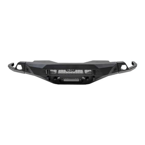
SPEC FRONT BUMPER
19-21 GMC SIERRA
FBGC1-02
TOOLS
REQUIRED
- T15 Socket
- 4mm, 6mm Allen head sockets
- 7, 10, 13, 15, 18, 21mm Sockets
- 22mm Wrench
- Tim Clip Tool, Zip Ties
- Metal Snips
- Safety Glasses
WARNINGS/CAUTIONS BEFORE STARTING INSTALLATION
Before you install this kit —
instructions, warnings, cautions, and notes contained in
this installation instruction guide. Consult your vehicle
owner's manual for proper disconnection of electrical and
lifting of vehicle if required for installation of this product.
This install may require some technical skills and
knowledge of basic mechanical work. If you do not feel that
you are capable of performing this install please take this
product to a trained professional.
After reading this guide please contact us with any
questions or concerns before installing product.
Customer Service: 855-680-9595
DV8 Offroad is not responsible for any bodily injury or harm to you
or your vehicle as a result of an improper install.
555 E Queen Creek Rd
Bldg A
Chandler, AZ 85286
WWW.DV8OFFROAD.COM
SKILL
LEVEL
- Intermediate
- 1 (you) to 2 persons
Moderate skill level required, you
can easily install it by yourself
however, additional help will be
useful
Read and understand all
INSTALLATION
PRODUCT
TIME
- 3.5 Hours
Time to install this should
take about an three and half
hours
Proper installation of this kit required knowledge of the factory
recommended procedures for removal and installation of original
equipment components. We recommend that the factory shop manual
and any special tools needed to service your vehicle be on hand during
the installation. Installation of this kit without proper knowledge of the
factory recommended procedures may affect the performance of these
components and the safety of the vehicle
• Always wear eye protection when operating power tools
Inspect all contents of this package to make sure product is not damaged
and all installation hardware has been included. If parts are missing from
kit, please be prepared to provide the following information
1. Name of purchase location
2. Bar Code on side of box
3. Date above bar code
4. Date inside box cover
NEED HELP?
MANUAL
REQUIRED
855-680-9595
Advertisement

Summary of Contents for DVB FBGC1-02
- Page 1 555 E Queen Creek Rd INSTALLATION MANUAL PRODUCT Bldg A Chandler, AZ 85286 WWW.DV8OFFROAD.COM SPEC FRONT BUMPER 19-21 GMC SIERRA FBGC1-02 TOOLS REQUIRED SKILL LEVEL TIME REQUIRED - T15 Socket - Intermediate - 3.5 Hours - 4mm, 6mm Allen head sockets...
- Page 2 INSTALLATION MANUAL Begin by unpacking all items and inspecting for missing pieces or damage. If you have any concerns, please contact the company the product was purchased from. Extra hardware may be included with the product. HARDWARE INCLUDED (16) M14x35 Hex Head Bolts (4) M10x30 Allen Head Bolts (16) M14 Lock Nuts (4) M10 Flat Washers...
- Page 3 INSTALLATION MANUAL STEP 2 | To disconnect the bumpers sensor wiring harness, reach up from underneath the vehicle in between the front bumper and inner fender as shown and disconnect the sensor harness. STEP 3 | Use a 10mm socket to remove the (4) bolts securing the bumpers lower valance.
- Page 4 INSTALLATION MANUAL STEP 4 | Use an 18mm socket to remove the (2) bumper mounting bolts on the inside of the frame rails. STEP 5 | Use a 15mm socket to remove the bumper supports from each side. STEP 6 | Use a plastic trim clip tool to pry the fender flare away from the upper bumper cover.
- Page 5 INSTALLATION MANUAL STEP 7 | To disconnect the upper bumper cover and fog lights from the fender, reach through the inner fender and use a 7mm socket to loosen the (2) hex head bolts that secures the upper covers retaining bracket on each side. Note: Only loosen these (2) bolts, do not remove them completely.
- Page 6 INSTALLATION MANUAL STEP 9 | With a firm grip pull the upper bumper cover away from the vehicle. STEP 10 | Continue to pull the upper bumper cover away from the vehicle. Note: A plastic trim clip tool can be used for added leverage for any tight spots or stubborn clips that may be difficult.
- Page 7 INSTALLATION MANUAL STEP 11 | To gain access to the upper bumper cover clips under the grille, the hood release and radiator cover will need to be removed. Use a T15 Torx tool to remove the (2) screws securing the hood release and slide the hood release off.
- Page 8 INSTALLATION MANUAL STEP 13 | Reach between the radiator support and the grille to release the upper bumper cover retaining clips. Remove the upper bumper cover and set it off to the side. 855-680-9595 NEED HELP?
- Page 9 INSTALLATION MANUAL STEP 14 | If your vehicle is equipped with an illuminated grille emblem, disconnect the (2) electrical plugs behind the driver side headlight. STEP 15 | Use a 10mm socket to remove the 3 hex head bolts securing the bottom of the grille.
- Page 10 INSTALLATION MANUAL STEP 16 | Use a 10mm socket to remove the (4) hex head bolts securing the top of the grille. Lift up on the grille and start to pull the grille away from the radiator support to expose the front camera electrical plug. STEP 17 | Disconnect the front camera electrical plug and set the grille...
- Page 11 INSTALLATION MANUAL STEP 18 | Use a trim clip tool to remove the clips retaining the air deflector. Pull the air deflector slightly forward to expose the (2) upper bumper bolts. STEP 19 | Use an 18mm socket to remove the (2) upper bumper mounting bolts.
- Page 12 INSTALLATION MANUAL STEP 20 | Use an 18mm socket to remove the front tow hooks. STEP 21 | Use an 18mm & 10mm socket to remove the crash bars. 855-680-9595 NEED HELP?
- Page 13 INSTALLATION MANUAL STEP 22 | Use a 10mm socket to remove both front inner fender supports. STEP 23 | Use a 15mm sockets to remove the (6) hex head bolts securing the factory bumper mounting plates. These mounting plates will not be used with the DV8 front bumper.
- Page 14 INSTALLATION MANUAL STEP 24 | Using a 15mm socket, remove the four bolts shown to remove the skid plate. STEP 25 | Lay the factory front bumper face down on a moving blanket or covered work bench. Use a 13mm socket to remove the (7) bolts securing the bumper supports.
- Page 15 INSTALLATION MANUAL STEP 26 | Using a trim tool, remove the clips holding the harness to the bumper. Remove the sensors from the sensor bezels by gently pulling the outside tabs apart and pull the sensor back away from the face of the bumper STEP 27 | With the harness and sensors removed, push in the two retainer...
- Page 16 INSTALLATION MANUAL STEP 28 | Once the disassembly of the factory bumper is complete, lay the center section of the DV8 bumper on a smooth surface to prevent damage. Install the M10 flat nuts provided onto the main mounting holes by pushing them into place.
- Page 17 INSTALLATION MANUAL STEP 30 | Install the skid plate using a #6 Allen head and M8 Allen hardware. Ensure the bottom of the bumper and bottom of the skid plate are even. STEP 31 | Place the provided foam onto the mating surface of the bumper or wings as shown.
- Page 18 INSTALLATION MANUAL STEP 32 | Using a 21mm socket and 22mm wrench, install the side wings onto the bumper using the provided M14 hardware. Ensure the top and face of the wings are aligned with the bumper. STEP 33 | If running LED pod lights, install the lights using the hardware provided with the light.
- Page 19 INSTALLATION MANUAL Using the hardware provided with the light, install the light onto the brackets and secure the light to the brackets. Using a 10mm socket and #4 Allen head, secure the brackets to the bumper. We are using the DV8 20” Elite LED Light bar for this install.
- Page 20 INSTALLATION MANUAL STEP 37 | Install the sensor bezels from the front of the bumper. Push the sensors into the bezel until they click into place. STEP 38 | Once wire harness is mounted, secure the harness to the bumper using zip ties on our built-in zip tie tabs.
- Page 21 INSTALLATION MANUAL STEP 39 | With assistance lift the bumper onto the truck and loosely secure it in place using the provided M10 hardware. 855-680-9595 NEED HELP?
- Page 22 INSTALLATION MANUAL STEP 40 | Ensure the bumper is centered on the vehicle. Use a 18mm socket to secure the M10 hardware. STEP 41 | Use the two provided lower brackets to secure the middle of the skid plate and winch plate using the M12 hardware.
- Page 23 INSTALLATION MANUAL STEP 42 | Use a 22mm wrench and a 21mm socket to secure the provided (3) M14 hardware and an 18mm socket and 19mm wrench to secure the upper (2) M12 bolts. . STEP 43 | Using factory hardware and 15mm socket, reinstall the two lower skid plate bolts.
- Page 24 INSTALLATION MANUAL STEP 44 | Mark your inner fenders below the lower bolt hole. This will be the trim line for the inner fenders. If easier, trim inner fender now leaving more material below the bumper than expected so that it can be tailored once the bumper is on.
- Page 25 INSTALLATION MANUAL STEP 47 | Reinstall upper bumper cover/fog lights by pushing clips back into place. Ensure to reconnect fog lights electrical plug. Secure the ends of the upper bumper cover by securing the (2) inner bumper bracket bolts and the bolt behind the fender flare using a 7mm socket.
- Page 26 INSTALLATION MANUAL STEP 49 | Moving to the top of the grille, reconnect plugs from step 14. Reinstall griller cover with factory trim clips. STEP 50 | Once all factory components are on, double check all connectors for the bumper, grille, camera, etc...
Need help?
Do you have a question about the FBGC1-02 and is the answer not in the manual?
Questions and answers