Table of Contents
Advertisement
Quick Links
Advertisement
Table of Contents

Related Manuals for Longest LGT-2500S


Summary of Contents for Longest LGT-2500S
-
Page 3: Table Of Contents
TABLE OF CONTENTS Foreword ....................3 Operator Qualifications ............... 3 Operator Training ................4 Product Description ................4 Safety Instructions ................6 Symbols ....................6 Precautionary Definitions ..............8 Personal Safety ................. 15 Protection of the Unit ................. 15 EMC Guidance..................17 Clinical Instructions ................ - Page 4 Inspections ..................34 Install the Handpiece Holder ............. 36 Connect the Handpiece ..............38 Connect the Power Cord ..............38 Operation ..................... 40 Preparing the Unit for Therapy ............40 Preparing the Patient for Therapy ............. 41 Starting the Treatment ..............42 Explanation of the Main Interface .............
-
Page 5: Foreword
Foreword Thank you for purchasing the LGT-2500S from our company. This manual is intended for users of the LGT-2500S. It contains general information on the instructions for safety, intended use, working principle, operation, maintenance, troubleshooting, and warranty. In order to maximize the use, efficiency, and working life of your unit, please read this manual thoroughly and become familiar with the controls, as well as the accessories, before operating the unit. -
Page 6: Operator Training
Operator Training Operators of the LGT-2500S must have been adequately trained in using this system safely and efficiently before they operate the unit. A documented, cross-functional review must be performed, as many times as necessary, in order to ensure that users can understand the instructions. - Page 7 The LGT-2500S is a compressed air operated ballistic shock wave generator featuring high-precision ballistic components in its applicator for shock wave generation. The motion and weight of the projectile accelerated by compressed air produce kinetic energy converted into sound energy when the projectile strikes an unmoved surface (shock transmitter).
-
Page 8: Safety Instructions
Safety Instructions Symbols 1. Medical Device Symbols Symbols Explanation Manufacturer Date of Manufacture Authorized Representative European Community Compliant with European Directive Medical Device (MDD) 93/42/EEC. (Notified Body Number 1639) Proper waste disposal for electrical and electronic equipment (WEEE) (See Disposal for instructions.) Type BF Applied Part(s) Refer to the instruction manual/ booklet... - Page 9 2. Package Symbols Symbols Explanation This Way Up Fragile, Handle with Care Keep Dry Temperature Limitation: between -20 and 55 degrees (centigrade). Humidity Limitation: less than 93%. Atmospheric Pressure Limitation: between 86kPa and 106kPa.
-
Page 10: Precautionary Definitions
Precautionary Definitions The precautionary instructions found in this section and throughout this manual are indicated by specific symbols. Understand these symbols and their definitions before operating this equipment. The definitions of these symbols are as follows: Text with a “CAUTION” indicator will explain possible safety infractions that could have the potential to cause minor to moderate injury or damage to equipment. - Page 11 Portable and mobile RF communications equipment can affect medical electrical equipment. No parts of the LGT-2500S can be serviced or maintained while the device is in use with the patient. Before using the device, check the unit to determine that all controls function normally (e.g., the STOP button ends treatment, the...
- Page 12 DO NOT use accessories other than those supplied with the unit or recommended by Guangzhou Longest Science & Technology Co., Ltd. The safety of other products has not been established, and their use could result in injury to the patient and degrade minimum safety.
- Page 13 Therefore, you must disconnect the male end of the power supply cord from the electrical outlet (mains power supply) to isolate it. The LGT-2500S is not intended for the treatment of kidney stones. In case of display failure or other apparent defects, switch the power off button immediately, disconnect the power cord from the power outlet, and notify a certified service technician.
- Page 14 Portable RF communications equipment (including peripherals such as antenna cables and external antennas) should be used no closer than 30 cm (12 inches) to any part of the LGT-2500S, including cables specified by the manufacturer. Otherwise, degradation of the performance of this equipment could result.
- Page 15 DO NOT give treatment in the area of metal implants. Place the unit on a flat surface during treatment and storage to prevent tipping or rolling. It is suggested not to apply more than 300 continuous pulses to the same spot.
- Page 16 The unit must be installed so that there is no danger to the patient, the operator, or other persons. Therefore, you must read the safety instruction and contraindications. Explosion hazard if the LGT-2500S is used in the presence of a flammable anesthetics mixture with air, oxygen, or nitrous oxide.
-
Page 17: Personal Safety
Personal Safety Before operating the unit, please read this instruction manual carefully and observe the information contained therein. Pay special attention to the list of contraindications. Before operating the unit each time, verify that: the unit has been correctly connected to the Mains Power Supply. ... - Page 18 an earthed socket outlet with earthing contact is available for connecting the unit. the power cable routing from the unit to the socket-outlet with earthing connection does not pose a danger to personnel or the patient. Ensure the unit is electrically earthed by connecting only to an earthed electrical service receptacle, conforming to the applicable national and local electrical codes.
-
Page 19: Emc Guidance
EMC Guidance This product needs special precautions regarding EMC and needs to be installed and put into service according to the EMC information provided. This device has been thoroughly tested and inspected to ensure proper performance and operation. Cable Information: Item Cable Length Cable Shielded... - Page 20 Guidance and manufacturer’s declaration – electromagnetic emission The LGT-2500S is intended for use in the electromagnetic environment specified below. The customer of the user of the LGT-2500S should ensure that it is used in such an environment. Electromagnetic Emission test Compliance environment –...
- Page 21 Guidance and manufacturer’s declaration – electromagnetic immunity The LGT-2500S is intended for use in the electromagnetic environment specified below. The customer or the user of the LGT-2500S should ensure that it is used in such an environment. Immunity IEC 60601 Compliance...
- Page 22 25/30 cycles 25/30 cycles during power mains Single phase: Single phase: interruptions, 61000-4-11 at 0° at 0° recommended that the LGT-2500S be powered from an uninterruptible 250/300 250/300 power supply cycles cycles battery. Power Power frequency frequency magnetic fields should...
- Page 23 Guidance and manufacturer’s declaration – electromagnetic immunity (Continued) The LGT-2500S is intended for use in the electromagnetic environment specified below. The customer or the user of LGT-2500S should ensure that it is used in such an environment. Electromagnetic Immunity IEC 60601 test...
- Page 24 Table: Test specifications for ENCLOSURE PORT IMMUNITY to RF wireless communications equipment Immunity Maximum Test Distance TEST Band power frequency Service Modulation LEVEL (MHz) (MHz) (V/m) 380 to TETRA 400 Pulse Modulation 18Hz 430 to GMRS 460, ± 5 Hz FRS 460 deviation 1 kHz sine...
- Page 25 5240 5100 to WLAN Pulse 5500 5800 802.11 Modulation 5785 217 Hz NOTE: a) For some services, only the uplink frequencies are included. b) The carrier shall be modulated using a 50 % duty cycle square wave signal. c) As an alternative to FM modulation, 50 % pulse modulation at 18 Hz may be used because while it does not represent actual modulation, it would be the worst case.
-
Page 26: Clinical Instructions
Stay current with the latest developments and medical publications on extracorporeal shock wave therapy for details on contraindications and side effects not known at the time of manufacturing. The LGT-2500S is contraindicated for the following: Pregnant woman... -
Page 27: Possible Side Effects
Bleeding tendency Patient with a pacemaker Neoplasms Cutaneous infections 10) Lung area 11) Spine 12) Cortisone therapy up to 6 weeks before the first treatment 13) Mental disorder (unable to express or have difficulty in communication) Possible Side Effects Side effects could occur after treatment with extracorporeal shock wave therapy. -
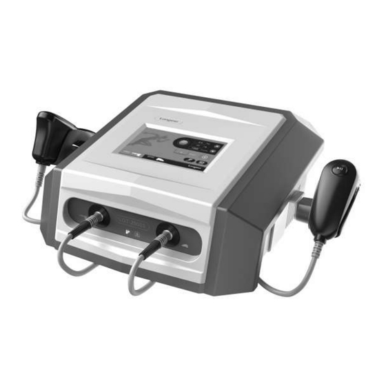
Page 28: Overview Of The Unit
Overview of the Unit Front View (right) Front View (left) Front View Back View... -
Page 29: Nomenclature
Nomenclature ① LCD touch screen ⑤ Vibration handpiece applicator ② General ⑥ Vibration handpiece handpiece applicator holder ③ General handpiece holder ⑦ Output socket of vibration handpiece ④ Output socket of general handpiece ① ON/OFF button ③ Cooling fan ② Switch socket ④... -
Page 30: Handpiece
Handpiece General Handpiece 1. Main part of the handpiece 2. Cable 3. Trigger 4. Transmitter 5. Rear cap 6. Shaft Vibration Handpiece 1. Main part of the handpiece 2. Trigger 3. Socket of transmitter 4. Transmitter 5. Cable... -
Page 31: Transmitter
Transmitter 1) The standard transmitter Ordering Item Name Remark Connect with General 25 0007 15mm Radial transmitter kit Handpiece Connect with General 25 0006 20mm Radial transmitter kit Handpiece Connect with Vibration 25 0062 25mm Vibration transmitter kit Handpiece 2) The optional transmitter Ordering Item Name Remark... -
Page 32: Optional Accessories
Optional Accessories Trolley Carrying Case... -
Page 33: Working Principle
Working Principle Power User Interface (touch screen) Sensor Control Three- General Proportional Solenoid Handpiece Compressor Valve Solenoid Tank Valve Valve Vibration Solenoid Valve Handpiece... -
Page 34: Technical Specifications
Technical Specifications General Extracorporeal Shock Wave Therapy Product Name Device Model LGT-2500S Reference Number (configuration) Software Release Version 565×395×194mm (with handpiece holders) Dimension (W×L×H) 390×395×194mm (without handpiece holders) Standard Weight 11.3 kg Performance Working Pressure 1.0-5.0 bar (adjustable by 0.1 bar) - Page 35 Working Frequency General Handpiece 1-22 Hz (adjustable by 1 Hz) Vibration Handpiece 1-35 Hz (adjustable by 1 Hz) Shocks 1-8000 shocks (step by 100 or 500 General Handpiece shocks) 1-10000 shocks (step by 100 or 500 Vibration Handpiece shocks Electrical Power Supply AC100-240V, 50/60Hz Rated Power...
-
Page 36: Preparation Before The Treatment
3. Check the external components and accessories for possible damage due to transport. 4. Verify that the packaging contains the following: Ordering Item Name Amounts Unit Number 25 0064 LGT-2500S(Config.III) Main Unit 25 0015 Power Cord piece... - Page 37 Ordering Item Name Amounts Unit Number 25 0027 Spare Fuses 3.15A pieces 25 0032 Certificate of Quality piece 25 0033 Warranty Card piece 25 0017 User Manual piece Vibration Handpiece 25 0065 suit (contains the following): Vibration Handpiece Applicator piece (with 1 piece of 25mm vibration transmitter and installed) Spare Seal Ring...
-
Page 38: Install The Handpiece Holder
(contains spacer, spacer rings, rubber seals, disc magnets and multi-specification seal rings) Other parts of the LGT-2500S are available as accessories on demand. Visit www.gzlongest.com for more information. Install the Handpiece Holder Take out the handpiece holder and install it on the main unit. -
Page 40: Connect The Handpiece
Connect the Handpiece Step 1: Hang the handpiece cable on the holder first and then connect the handpiece. Step 2: Connect the handpiece connector into the output sockets. (PS: Please pay attention to the RED point indicator should be aligned with the red dot on the device, as shown in the following picture.) Connect the Power Cord 1. - Page 41 3. Press the ON/OFF button on the backside of the device to start the unit.
-
Page 42: Operation
Operation Preparing the Unit for Therapy The unit has been completely assembled in the factory and is ready for use except for the handpiece and the power cord connection. Proceed as follows in order to prepare the unit for operation: ... -
Page 43: Preparing The Patient For Therapy
(mainly bullet and metal pipe). Preparing the Patient for Therapy Before applying the LGT-2500S to the patient, you need to do the following step to maximize the treatment effect and minimize the risk of skin irritation that may cause: Thoroughly wash the skin on which you intend to administer therapy with mild soap and water or an alcohol wipe;... -
Page 44: Starting The Treatment
Starting the Treatment Icons Preset Protocols User-defined Protocols Down Selection of Transmitter Start Stop Channel of General Handpiece Channel of Vibration Handpiece Turn on the ON/OFF button at the backside of the device; around 30 seconds later, the main interface appears, and you can reset the treatment parameters here. -
Page 45: Explanation Of The Main Interface
Explanation of the Main Interface Parameter Setting Parameters General Handpiece Vibration Handpiece Transmitter 20R, 15R, 15F, 15D, 6A, 36R 40V, 25V, 10V Pressure range 1.0-5.0 bar 1.0-5.0 bar step 0.1 bar 0.1 bar default 2.0 bar 2.0 bar Frequency range 1-22 Hz 1-35 Hz step... -
Page 46: Handpiece Connection Error Prompt
When Choose the General Handpiece for Treatment Preset Protocols The LGT-2500S has programmed more than 10 types of protocols for the most popular musculoskeletal diseases to use. Please follow the guidance below. STEP 1: Press the preset protocols button in the main interface then you will enter the interface below. - Page 47 STEP 2: Choose the indication that you need and press the button. The below interface will show.
- Page 48 STEP 4: Press and then pull the trigger in the handpiece and hold on for 2 seconds to start the treatment. NOTE: Pressure and Frequency are adjustable during the treatment (Pressure adjustable with 0.1 bars; frequency adjustable with 1 Hz), while the number of shocks cannot be adjustable during the treatment.
-
Page 49: User-Defined Protocols
User-defined Protocols The LGT-2500S allows doctors to design and save their treatment parameters according to different patients’ conditions. Please follow the guidance below. Icons Choose a saved protocol and Set up a new protocol enter the treatment interface Delete a protocol... - Page 50 STEP 1: Press the button to enter the User-defined interface, as below shows. STEP 2: Press the button to set up a new protocol and set the treatment parameters you need.
- Page 51 STEP 3: Touch the blank square in front of the User-defined protocol to name your protocol, and then touch Enter to save it. STEP 4: Touch 20R mm to choose the transmitter. STEP 5: Press the blank square in front of the Treated Area to choose the treatment part.
- Page 52 STEP 6: Set treatment parameters: pressure, frequency, and number of shocks. (You can adjust them by touching the UP and DOWN button on the right-hand side.) STEP 7: Press the button to save this protocol, and the below interface will show. If you want to start the treatment from this step, please press the button, and you will enter the treatment interface.
-
Page 53: System Setup
System Setup Press the button in the right corner of the main interface to enter the System Setup interface. Press the button, and the following interface will appear. -
Page 54: Language
Press the button, and the following interface will appear. Language Press the button to switch languages. Available languages are English, German, French, Italian, Spanish etc. Touch the language and then touch the OK button. -
Page 55: System Information
System Information Press the button to check the basic information of the device. Shocks History Touch the button, and you will be able to check the history shocks of the device. -
Page 56: Software Update
Software Update You can update the software of the LGT-2500S to the latest version by USB port. (This should be conducted by your local distributor, and extra cost might be requested) NOTE: There is a USB socket at the back side of the main unit, and that is only for software updates. -
Page 57: Cleaning And Disinfection Instructions
Cleaning and Disinfection Instructions Please turn off and unplug the device before the cleaning and disinfection operation; For the main unit cleaning, what is recommended are a clean, soft, damp cloth for stains, and a clean, soft, dry cloth for dust on the surface of the main unit;... -
Page 58: Maintenance Instructions
Maintenance Instructions Read this maintenance instruction thoroughly before doing any maintenance. The manufacturer will provide circuit diagrams, component part lists, descriptions and calibration instructions to assist service persons in parts repair. To preserve product warranty, functionality and product safety, we recommend using only original spare parts. - Page 59 Step 1: Disassemble the metal pipe and the bullet. Turn off and unplug the device first, and then unplug the handpiece from the main unit. Unscrew the transmitter and the other end of the metal pipe from the handpiece body. Use a small screwdriver to put through the 2 holes on the...
- Page 60 metal pipe and then gently pull the metal pipe out of the shaft. Take out the bullet from the metal pipe, and then clean the metal pipe and the bullet. Step 2: Clean the metal pipe. We suggest using the WD-40 multifunctional product to clean the metal pipe.
- Page 61 Step 4: Make the bullet fall from one end of the metal pipe to the other end. Repeat this several times. Step 5: Test the performance. Reload metal pipe and bullet to the handpiece and test performance. Methods: adjust parameters when the device is working and listen to the sound of the handpiece.
- Page 62 When you are reloading the metal pipe and bullet, make sure the transmitter is in good condition and without any damage, and make sure the transmitter is well installed in the handpiece. Falling off the transmitter from the handpiece may harm the patient during the treatment.
- Page 63 Step 3: Put a new spacer into the handpiece and make some adjustments with tweezers. Make sure the spacer is settled firmly.
- Page 64 Step 4: Reinstall the handpiece and test the performance (start the device and listen to the sound of the handpiece) When testing the performance, make sure the transmitter is in good condition and without any damage, and make sure the transmitter is well installed in the handpiece.
-
Page 65: Maintenance Period
Maintenance Period Number of Metal Yellow Rubber O-ring Bullet Transmitter Shocks Pipe Spacer Seal (Seal Ring) 100,000 200,000 300,000 400,000 500,000 600,000 700,000 800,000 900,000 1,000,000 Cleaning Replacement Metal Pipe Bullet Transmitter Yellow Spacer Rubber Seal O-ring (Seal Ring) Suggestion: Some gel may remain inside the transmitter after treatment, which will cause mildew if without cleaning for a long time. -
Page 66: Expected Useful Life
Expected Useful Life The expected useful life of this main unit is 5 years. For information about the useful life of the handpiece, please see the Maintenance Period of this chapter. Disposal According to EC Directive – WEEE (Waste Electrical and Electronic Equipment), the equipment must not be disposed of as unsorted municipal waste and must be collected separately. -
Page 67: Troubleshooting
Troubleshooting NOTE: If the following measures fail to alleviate the problem, please call the distributors. Problems Possible Causes Solutions 1. Lack of power; 1. Check whether the power response Fuse might plug socket after starting burned out. instrument are plugged or not; the device 2. -
Page 68: Assistance
For any assistance intervention and original spare parts please contact the manufacturer at the following address: GUANGZHOU LONGEST SCIENCE & TECHNOLOGY CO., LTD. Add: Floor 3&4, Building B&C, #96 Chuangqiang Road, Ningxi Street, Zengcheng District, 511399, Guangzhou, P.R. China... -
Page 69: Warranty
To validate the warranty, please complete the Warranty Card and send it with the copy of the original invoice to the email address service@longest.cn within 7 working days of purchase. 2) Warranty for the handpiece Warranty claims will only be accepted if the handpiece is returned in its complete and original state. - Page 70 Revision kit/transmitter kit will be out of warranty once anyone of the above two items goes into effect. 4) Warranty for other parts Consult local distributor or LONGEST for more information. 5) This warranty does not cover: Replacement parts or labor furnished by anyone other than the manufacturer, the authorized dealer or a certified company service technician.
Need help?
Do you have a question about the LGT-2500S and is the answer not in the manual?
Questions and answers