Table of Contents
Advertisement
Quick Links
Advertisement
Table of Contents

Summary of Contents for AGEON AG Drive
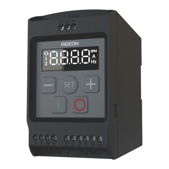
- Page 1 Technical guide FREQUENCY INVERTERS AG Drive Mini XF2-05-1P1 | XF2-10-1P1...
-
Page 2: Table Of Contents
Summary Chapter 1 – Quick start ................... 3 Parameters list ............................3 Understanding the Human Machine Interface (HMI) ................. 6 HIM messages ............................6 Chapter 2 – Safety instructions ................8 2.1 Safety symbols ............................... 8 2.2 Safety precautions ............................9 2.3 Grounding .............................. -
Page 3: Chapter 1 - Quick Start
Chapter 1 – Quick start Parameters list Factory Reg. Param. Function Range of values default value Modbus Output frequency P001 0,00 to 500.0 Hz visualization DC bus voltage P002 0 to 400 V visualization Output current P003 0 to 15.0 A visualization Output voltage P004... - Page 4 P022 Start-up frequency P023 to P024 5.00 Hz Motor frequency low P023 0.00 Hz to P024 5.00 Hz limit Motor frequency high P024 P023 to 500.0 Hz 60.00 Hz limit 0 = frequency P028 Standard display unit 1 = ampere 2 = RPM P041 Torque Boost...
- Page 5 0 = HIM keyboard command 1 = digital inputs command: DI 1 = start/stop DI 2 = rotation direction Inverter command mode P302 selection 2 = digital inputs command: DI 1 = forward DI 2 = backward 3 = Modbus command.
-
Page 6: Understanding The Human Machine Interface (Hmi)
Understanding the Human Machine Interface (HMI) Figure 1 – Human Machine Interface (HMI) Number Name Function When this LED is on, it indicates a reversal in the rotation direction. HIM display. Indicates that the values displayed are in revolutions per minute. Indicates that the values displayed are in Ampere. - Page 7 This indicates that the inverter is ready to operate. In this state, the motor is awaiting a start command. This indicates that the input voltage is insufficient to operate the motor. This indicates that the inverter has been disabled via the DI2 digital Stop input.
-
Page 8: Chapter 2 - Safety Instructions
If you encounter this error message on your device, please reach out to E007 – Hardware failure AGEON technical support for assistance. This error occurs if no valid Modbus message is received within the E009 – Communication failure watchdog time duration (P704) or in case of communication loss with with remote HMI or Modbus the Remote HMI. -
Page 9: Safety Precautions
Safety precautions DANGER! When in operation, this device can cause electric shock if handled incorrectly. Not following these recommendations may result in death, injuries, or damage to the equipment. The installation and maintenance of the inverter must be performed by a professional qualified for this task;... - Page 10 NOTE This device is a source of electromagnetic emissions; therefore, the following information must be taken into consideration: Whenever possible, use shielded power cables with grounded shielding. Keep other equipment and devices with low electromagnetic immunity away from the inverter, motor, or adequately protected. WARNING! This device should not be used as an emergency stop equipment.
-
Page 11: Grounding
NOTE Use cables and connectors compatible with the installed power and in accordance with local regulations. DANGER! The inverter and the motor must be properly grounded for the safety of the user and other equipments. Failing to comply with the following guidelines may result in death or serious injuries and can cause irreversible failure to the motor, inverter, and other equipments. - Page 12 200 Vac and 240 Vac for an efficient inverter operation; - Increase ramp-down time; - If the error persists, contact AGEON technical support. - Verify the input voltage of the inverter and ensure the power supply is appropriate;...
- Page 13 - Ensure that the shaft of the motor is not blocked; - Ensure that the load is suitable for the motor power; - If the error persists, contact AGEON technical support. - Ensure there is no short circuit between the motor supply phases;...
-
Page 14: Chapter 3 - Installation And Assembly
DANGER! The adaptation of the Power supply must be carried out by qualified and authorized professionals. WARNING! Never use compressed air equipments to clean the inverter. Never remove the heat sink. Use appropriate tools to clean the fins of the heat sink to ensure proper air circulation. Chapter 3 –... -
Page 15: Mechanical Installation
3.2 Mechanical installation 3.2.1 Dimensions The product dimensions are presented in the Figure 3 below. Figure 3 – Product dimensions. 3.2.2 Positioning and Drilling It is possible to install the inverter using the mounting holes (Figure 4) or DIN-35 rail (Figure 5). The recommended mounting spacing from Figure 6 and Figure 7 must be respected. - Page 16 Figure 5 - Detail for Mounting on DIN-35 Rail. NOTE If the installation environment experiences excessive vibration, it is not recommended to use DIN rail fixation. Whenever possible, use the mounting holes with appropriate screws for securing the device.
- Page 17 Figure 6 - Detail for DIN-35 lail mounting spacing. WARNING! WARNING! Never install inverters in a stacked configuration, meaning with horizontal spacing less than 20 mm, even if the vertical distance is greater than 80 mm. Risk of irreversible failure due to poor air circulation in the fins of the heat sinks.
- Page 18 Figure 7 – Best practices for mechanical installation.
-
Page 19: Electrical Installation
WARNING! Avoid placing components that generate excessive heat near the inverter, even if the minimum distance is met. This contributes to more efficient equipment operation and reduces the risk of overheating. 3.3 Electrical installation 3.3.1 General aspects regarding electromagnetic compatibility. ... - Page 20 Figure 9 - Best practices for cable tray installation. NOTE Power cables should not run alongside control cables in cable trays or conduits unless the control cable has suitable insulation for this purpose. When control cables lack appropriate insulation, place them in separate cable trays with a minimum distance of 500 mm, as shown in Figure 9.
- Page 21 Figure 10 - Best Practices for Cable Routing. When power cables to supply the inverter and/or other equipment are installed in trays parallel to the motor cable tray, ensure a distance of at least 300 mm between them, as shown in Figure 10. Figure 11 represents an installation that follows some guidelines according to best practices for electromagnetic compatibility.
- Page 22 Figure 1 - Best practices for electrical panel installation.
-
Page 23: Selection Of Power Supply Wiring
3.3.2 Selection of power supply wiring DANGER! The wiring must be sized according to the current technical standards. The use of incorrectly sized and/or low-quality cables can result in death, injury, or irreversible damage to the equipment. It is recommended to use specific multipolar cables for frequency inverter applications. The recommended cable has three symmetrical conductors for the phases, three symmetrical conductors for grounding (PE) and copper (SCu) or aluminum shielding. -
Page 24: Selection Of Digital And Analog Signal Wiring
When the conductors are smaller Copper (Scu) than 10 mm², as an alternative, you Acceptable or aluminum can use this model of cable. Table 3 – Recommended cable options. Legend: U, V, W – Phase conductors PE – Ground conductor SCu –... -
Page 25: Identification Of Command Terminals
In Figure 13, it is shown the motor power terminals and the grounding terminal for the motor frame. The inverter output is 220 VAC (three-phase). Figure 3 – Motor power supply 3.3.5 Identification of command terminals. Command terminal number Description 10V power supply, 25 mA capacity Analog input for voltage or current. - Page 26 Digital inputs Figure 5 - Example of digital input connection. Analog input with potentiometer connection Figure 6 - Wiring diagram for potentiometer motor speed control.
- Page 27 Analog Input in voltage function with external electrically isolated device Figure 7 - Wiring diagram for external device via voltage signal (isolated). Analog Input in voltage function with nonisolated external device Figure 8 - Wiring diagram for external device via voltage signal (nonisolated).
-
Page 28: Chapter 4 - Parameters Description
WARNING! Incorrect sizing of protection fuses and/or cable can cause irreversible damage to the equipment as well as the electrical installation. Properly size the fuses according to Table 4 and in accordance with current standards. To protect the inverter output, an ultra-fast gR or gS type fuse, specifically designed for semiconductors protection, should be used with a current rating according to Table 3. - Page 29 WARNING! P001 - Output frequency visualization Indicates the output frequency to the motor, in Hertz (Hz). P002 - DC bus voltage visualization Indicates the voltage in the DC bus, in Volts (V). P003 - Output current visualization Indicates the inverter output current to the motor, in Amperes (A). P004 - Output voltage visualization Indicates the inverter output voltage applied to the motor, in Volts (V).
- Page 30 For more detailed information, please refer to section ‘2.4 – Failure sollutions’. P009 - Inverter software visualization Indicates the software version installed in the inverter. 4.1 Writting parameters P007 - Parameter to block changes It is used to lock or unlock any change in the inverter parameters. When accessing the parameter P007, it can have the following values: ...
- Page 31 Defines the time, in seconds, for the motor to accelerate to the nominal frequency set in parameter P602. This ramp will also be applied whenever there is an increase in the frequency reference. The acceleration has a linear profile (ramp) as shown in Figure 19. The acceleration time when reference changes will always be proportional to the time defined in P011.
- Page 32 2 = When the output is activated, the motor will accelerate following the acceleration ramp defined in P011 up to the frequency defined in P022. P022 - Start-up Frequency If P021 = 2, after activation, the motor will accelerate following the acceleration ramp defined in P011 up to the frequency defined in this parameter.
- Page 33 P043 - Switching Frequency This parameter allows you to configure the switching frequency of the IGBTs. For optimal configuration of this parameter, consider the factors described in Table 5. Motor IGBT temperature 5 kHz HEAT 10 kHz NOISE 15 kHz Table 5 - Relationship between switching frequency and acoustic noise/temperature.
- Page 34 Figure 20 – Overload curve. This parameter can be deactivated, in which case the motor would no longer have overcurrent protection. However, the inverter continues to protect against hardware short-circuit (E006) and overtemperature (E004). P053 - Auto-reset A time (3 to 255 seconds) can be set, after the error, during which the inverter will automatically restart.
- Page 35 Where: AI’ is the internal value effectively used by the inverter; AI is the external value, i.e., the actual value read at the analog input; G is the value of P100. Example: If the gain is 50% (P100 = 50.0), and the amplitude of the signal at the input is 5.0 V (AI = 5.0 V), the final voltage for the frequency reference will be 2.5 V (AI’...
- Page 36 Electronic Potentiometer (digital inputs DI2 and DI3): while the state of DI2 is high, the output frequency is continuously increased. Similarly, while the state of DI3 is high, the output frequency is continuously decreased. If the inputs are in a low state, the frequency remains unchanged.
- Page 37 0 - Normal direction (forward): It will always remain in the normal direction, regardless of any command; 1 - Reverse direction (return): It will always remain in the reverse direction, regardless of any command; 2 - Direction defined by commands: Depending on the direction command (see parameters P302 and P304).
- Page 38 WARNING! It is crucial to adjust this parameter correctly as it determines the V/f curves through which the control method operates. Incorrect adjustment can lead to permanent damage to the motor. P603 - Motor rated rotation This parameter should be adjusted according to the information on the motor specifications plate. P701 - Inverter address (Modbus) Defines the address of the inverter on the Modbus network.
- Page 39 Odd: the number of 1 bits is counted. If the count is odd, the parity bit is set to 0 so that the total number of 1 bits in the message is odd; if the count is even, the parity bit is set to 1. Table 3 –...
-
Page 40: Chapter 5 - Modbus Rtu Communication
Chapter 5 – Modbus RTU Communication 5.1 Preliminary information The AG Drive inverter family has native Modbus communication. However, for the AG Drive Mini model, the Serial-RS-485 adapter must be purchased separately. The implemented protocol is Modbus RTU, widely used in the industry. Modbus communication allows the device to be controlled remotely and be included in a communication network. - Page 41 Figure 10 - Daisy Chain connection example. WARNING! The use of communication adapters or similar devices should be tested and validated before operation. Use only devices that comply with safety standards. The other connection methods are acceptable or should be avoided as indicated in Figure 22.
- Page 42 Figure 11 - Network connection methods. The Table 10 presents the wiring diagram of the RS-485 Serial Adapter. The adapter should be connected to the Mini USB port located on the right side of the inverter. Connectors Function Description Ground. Common point of the circuit. Do not mistake with protection ground or panel ground.
-
Page 43: The Protocol
P302 - Inverter command mode selection: Set this parameter to 3 for command selection exclusively via Modbus. If this parameter is not configured, attempting to command the inverter via Modbus will result in the inverter sending exception message 4. ... - Page 44 Start Address Function Data 3.5 times the 3.5 times the 8 bits 8 bits N x 8 bits 16 bits character duration character duration In Modbus communication, devices interpret the start and end of a message based on a specific silence time on the bus.
- Page 45 is odd, the parity bit is 0. If there is a parity error in the request, XF2 simply does not provide any response. The only type of Modbus RTU protocol variable implemented in XF2 is the holding register. The implemented tasks are 03 and 06, described below: ...
-
Page 46: Controlling The Inverter Via Modbus
Request (Master) Answer (Slave) Field Value Field Value Slave address Slave address Function code Function code Register number (Hi) Register number (Hi) Register number (Lo) Register number (Lo) Value (Hi) Value (Hi) Value (Lo) Value (Lo) CRC Lo CRC Lo CRC Lo CRC Lo CRC HI... - Page 47 WARNING! Set the command selection parameters (P301) and frequency reference (P302) for Modbus only after the validation and preliminary tests of the motor and load to be controlled. Risk of unintentional activation. For the activation of the inverter, a set of registers has been defined with basic command functions. These registers are described in Table 14.
-
Page 48: Recommendations For Modbus Communication Implementation
5.4 Recommendations for Modbus Communication Implementation This section describes some recommendations and precautions to assist in the correct implementation of Modbus communication. When there is a connection between devices within the same building but in different panels, it is recommended to ensure equipotential grounding;... -
Page 49: Chapter 7 - Technical Specifications
Chapter 7 – Technical specifications Model Parameters XF2-05 XF2-10 Maximum motor power (in HP) 0.5 hp 1 hp Rated output current 2.6 A 4.0 A Maximum output current 3.4 A 5.2 A Maximum input current 5.1 A 7.8 A Power supply Single-phase / Two-phase Rated voltage 200 to 240 VAC RMS... - Page 50 (48) 3028-8878 (48) 99996-0430...
Need help?
Do you have a question about the AG Drive and is the answer not in the manual?
Questions and answers