Table of Contents
Advertisement
Quick Links
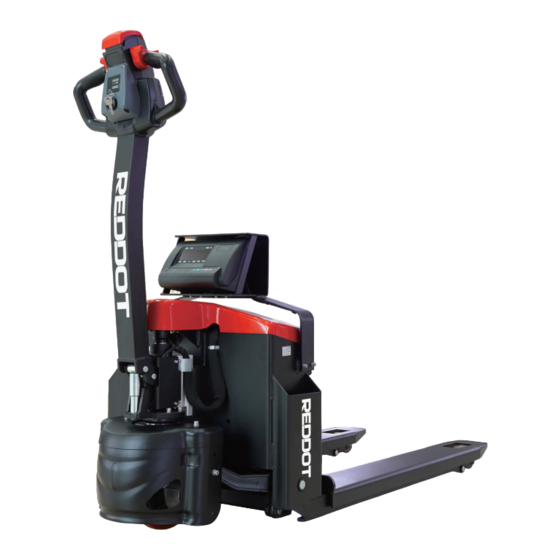
EPT20-15ET2P
1.5 ton electronic scale electric truck
Small size, light weight, easy to operate;
Different needs, multiple choices;
Add intelligent weighing system, more efficient;
Parts kits that have been tested in the market
for many years, the quality is guaranteed.
REDDOT EQUIPMENT LIMITED
REDDOT electric trucks have passed the anti-slope test and verification. The products meet the national
TSG 07-2019, TSG N0001-2017, GB/T10827.1, GB/T26949.1, GB/T18849 standards, please rest assured to
buy.
V2208.01
Advertisement
Table of Contents

Summary of Contents for Reddot EPT20-15ET2P
- Page 1 Parts kits that have been tested in the market for many years, the quality is guaranteed. REDDOT EQUIPMENT LIMITED REDDOT electric trucks have passed the anti-slope test and verification. The products meet the national TSG 07-2019, TSG N0001-2017, GB/T10827.1, GB/T26949.1, GB/T18849 standards, please rest assured to buy.
-
Page 2: Product Features
PRODUCT FEATURES Standard sensors Intelligent weighing system Parts kits that have been tested The new weighing system comes standard with 6 in the market for many years, the sensors and a split weighing tray to improve the quality is guaranteed performance and service life of the vehicle. -
Page 3: Product Parameters
PRODUCT PARAMETERS REDDOT Manufacturer Model designation EPT20-15ET2P Rated capacity 1500 Load center distance Load distance 934/990 Wheelbase 1272/1331 Service weight (include battery Axle loading, laden driving side/loading side 567/1128 Axle loading, unladen driving side/loading side 155/40 Tyre type driving wheels/loading wheels PU/ PU Tyre size, driving wheels(diameter×width... -
Page 4: Line Graph
LINE GRAPH SELECTION TABLE Serial number Options EPT20-15ET2P Fork length 1150 800~1300 Fork width 560 685 Minimum fork height Type of load wheel Loading wheel material Driving wheel Battery capacity 65Ah 85Ah Charger 24V-10A Electricity meter Front panel LOGO 2.16... - Page 5 INSTRUCTIONS FOR INTELLIGENT WEIGHING SYSTEM Chapter 1 Main Parameters Serial number Options Content Model designation XK3190-A12+(E) Weighing indicator Accuracy Level 3,n=3000 Sampling speed 10 times/sec Sensor sensitivity range 1.5~3mV / V Graduation value 1/2/5/10/20/50 Optional Display 6-digit LCD/LED, 6 status indications Adopt serial output mode, current loop signal, Large screen display interface transmission distance ≤2000 meters...
-
Page 6: Chapter 2 Appearance And Connection
Chapter 2 Appearance and Connection 1. Schematic diagram of instrument display and keyboard function Figure 1 (Schematic diagram of instrument chassis) Figure 2 (Schematic diagram of instrument keyboard) switch (A12+E does Function Peeling Zero not have this key) -
Page 7: Keyboard Function
2. Keyboard function 1. [ # ]: Press and hold this key during POST to enter calibration mode. 2. [ Function ]:In weighing state, press this key for more than 5 seconds to enter user setting mode. Press this key for less than 5 seconds to enter the counting state. 3. - Page 8 Figure 4 (connection diagram of meter, computer and large screen) 4.The connection between the large screen and the instrument (optional function) The large screen signal is a 20mA constant current current loop signal, which is serially output in binary code with a baud rate of 600. Please refer to Figure 4 for the connection method between the meter and the large screen.
-
Page 9: Chapter 3 Operation Instructions
(1) Continuous mode: The data transmitted is the current weighing (gross, net or tare). Gross weight format is: ww000.000kg or ww000.000lb Net weight format is: wn000.000kg or wn000.000lb Tare format is: wt000.000kg or wt000.000lb Note: The above decimal point position is determined according to the decimal point position setting of the instrument. -
Page 10: Counting Function
4. Counting function In the weighing display state, press the [Function] key to enter the counting state, display count, put a certain amount of heavy objects, after it is stable, Press[ * ]key to display C00000, press[tare]key to move the selection position corresponding to the small triangle, Press[Zero]key, the corresponding digit of the small triangle is incremented by one, input the number of samples,... -
Page 11: Chapter 4 Maintenance And Precautions
9、P9 x —— Start-up zero range x=3: 20 mins x=1: 2%FS x=4: 30 mins x=2: 4%FS 3、P3 x —— Baud rate setting x=3: 10%FS x=1: 9600 x=4: 20%FS x=2: 4800 x=5: 100%FS x=3: 2400 x=6: Prohibit boot to zero x=4: 1200 10、P10 x ——... - Page 12 ▲!Before plugging and unplugging the sensor cable, the power supply of the instrument must be cut off (shut down)! ▲!Before plugging and unplugging the large screen connection cable, you must first cut off the power of the instrument and the large screen! ▲!Before plugging and unplugging the communication cable, the power supply of the instrument and the host computer must be cut off! 4.
- Page 13 10. Meter charging instructions: When charging the A12+ meter, you need to plug in the AC power first, turn on the rocker switch behind the meter, the green AC indicator on the meter panel is on, and the meter enters the charging state. When the LCD display is turned on and the meter is working normally, if the AC power is plugged in, the meter also enters the charging state.
-
Page 14: Calibration Specification
CALIBRATION SPECIFICATION 1. General calibration method Before calibration, please insert a short-circuit ring at the calibration switch CN7 of the main board, and the calibration switch is turned on by default. During the boot initialization process, press and hold the [#] key until the stroke self- test is over, the meter will enter the calibration state and display [d X ]. - Page 15 3. Maximum weighing setting: Display 【FULL 】 —— Press【Tare】key to enter the digital input state. Display 【0 0 0 0 0 0】 —— Press the [Tare] key, and move the symbol ▼ to the right to select the digital input position, ——...
- Page 16 2. The rapid calibration method During the boot initialization process, press and hold the [#] key until the stroke self-test is over, the meter will enter the calibration state and display [d X ]. Follow the steps below step by step, 1.
Need help?
Do you have a question about the EPT20-15ET2P and is the answer not in the manual?
Questions and answers