Table of Contents
Advertisement
Dehumidifying Hot Air Dryer
DMS2-80,120,170,240
DMZ2-40,80,120
Instruction manual
WARNING
Thank you very much for purchasing the product.
Read the manual carefully and operate the device properly.
In addition, when operate the device, please keep the manual near the device for
reference when necessary.
Be sure to confirm a set value of each setting part when you install it on
customer's place, and secure it so that there is no error.
Separable type
Integrated type
Issued in September. 2010
Advertisement
Table of Contents

Subscribe to Our Youtube Channel
Related Manuals for Matsui DMS2-80


Summary of Contents for Matsui DMS2-80
- Page 1 Dehumidifying Hot Air Dryer DMS2-80,120,170,240 DMZ2-40,80,120 Instruction manual WARNING Thank you very much for purchasing the product. Read the manual carefully and operate the device properly. In addition, when operate the device, please keep the manual near the device for reference when necessary.
-
Page 2: Table Of Contents
CONTENTS The item should put on the important position, so please read the manual carefully and understand it thoroughly before the installation. Page TABLE OF CONTENTS ………………………………………………………………… I~II INTRODUCTION ……………………………………………………………………………… 1. Products Covered 2. Target Readers 3. Warranty Chapter 1 Safety Precautions -----------------------------------------------------------------1 Chapter 2... - Page 3 CONTENTS Page Chapter 4 Preparation for Operation 1. Inspecting inside of the hopper ------------------------------------------------34 2. Condition confirmation of each unit and feeding of the resin --------------40 Chapter 5 Operating Procedures --------------------------------------------------------43 Chapter 6 Maintenance -------------------------------------------------------------------------44 Chapter 7 Alarms function -----------------------------------------------------------------50 Chapter 8 Troubleshooting ------------------------------------------------------------------52...
-
Page 4: Introduction
Dryer and the maintenance as well as the inspection measures. 2. The readers The customers who whether use Dehumidifying Hot Air Dryer by MATSUI Company for the first time or have the experience to use the product all should read the manual carefully. 3. Maintenance... -
Page 5: Chapter 1 Safety Precautions
Chapter 1 Safety Precautions Using the device please must observe the notice items. Notice items Notice content The device is a dehumidifying unit that only the resin pill is available. The application of Other materials will cause the malfunction of the device. As the the device malfunction caused by the materials except the resin pill is not within the maintenance range, please contact us before using other... - Page 6 Chapter 1 Safety Precautions Notice items Notice contents Maintenance inspection Do not stand or seat on the device. Do not put your legs on it. Do not take the device as the footstool or climbing tool. In order to keep the functions; it is necessary to clean the filters. Please clean them regularly and do not operate the device if the filters are not clean.
-
Page 7: Chapter 2 Explanation Equipment
Chapter 2 Explanation Equipment 1.The summarization of the installation The device is a drying machine with the resin pill as the drying material. The device uses the sorbent to dehumidify the air and then sends the dried air into the funnel to dry the resin. Because the moisture in the air is dehumidified by the sorbent ,the stable drying condition is obtained. -
Page 8: Equipment Composition
The device consists of the recorded machines and apparatuses. Please refer to the types of this item and device brand to Confirm that type you want to purchase. < Type example > DMS2-80①-25②-③ Drying filter capacity Classifying mark of the dehumidification unit ① Technical criterion of drying temperature<the set upper limit of the drying temperature>... -
Page 9: The Check And Receiving The Goods
— Organic whole dehumidifier (organic whole pallet type) — The title of the machine The sate of goods arrival On the occasion of recycling ※the main body of the device dehumidifying unit drying funnel common use pallet connecting hose. Picture 1 ※DMS2-80-25 type - 5 -... - Page 10 Title of the machine The state of goods arrival On the occasion of recycling specification ○Dehumidifying Picture 2 The picture shows DMS2-80 type ○Drying funnel Picture 3 The picture show HD-25 type ※Hold in the ethylene resin bag - 6 -...
- Page 11 Chapter 2 Explanation Equipment The title of the machine The state of goods arrival ○Input and output stand ○4 capped bolts(forming machine for input and output) ○4 bolts with 6 angles ○4 screw caps with 6 angles ○4 flat brushes (those above are used to fix drying funnel and output stand) Picture 4...
-
Page 12: The Title Of The Parts
Chapter 2 Explanation Equipment 4.The titles of the parts <The main body of the dehumidify unit> DMS2-80,120/DMZ2-40 - - reclaim exhuaust dehumifying air(IN) over dehumidifving(OUT) bolts with holes (4) power label power switch control panel flat knob standby button Control on button warning label buzzer notice label... - Page 13 Chapter 2 Explanation Equipment <The main body of the unit> dehumidify DMS2-170,240/DMZ2-80,120 - - Dehumifying air(IN) reclaim exhuaust over dehumidifying air(OUT) bolts with holes (4) power label control panel power switch buzzer flat knob standby button Control on button warning label notice label drying filter reclaim filter...
- Page 14 Chapter 2 Explanation Equipment <Drying hopper> - - - HD-10,15,25,50 type - - - Hook plate for lifting Temperature sensor Thermostat U-bolt Exhaust pipe Suction pipe Catchclips(3) Cylindrical section Heater box Level glass Relay box Warning label Power supply sticker Catchclips (2) Heater cord Power cord...
- Page 15 Chapter 2 Explanation Equipment <Drying hopper> - - HD-75,100,150,200 type - - Hook plate for lifting Thermostat Temperature sensor U-bolt HD-75,100 HD-150,200 Exhaust pipe Suction pipe Catchclips(3) Warning label Heater box Cylindrical section Relay box Cleaning door Power supply sticker Adjusting fastener Heater cord Level glass...
- Page 16 Chapter 2 Explanation Equipment <Drying hopper> - - HD-250,300 type - - Temperature sensor thermostat Exhaust pipe Suction pipe Warning label Heater box Cylindrical section Relay box Level glass Power supply sticker Heater cord Relay cord Conical section Hot air pipe Base Set pin (Handle)...
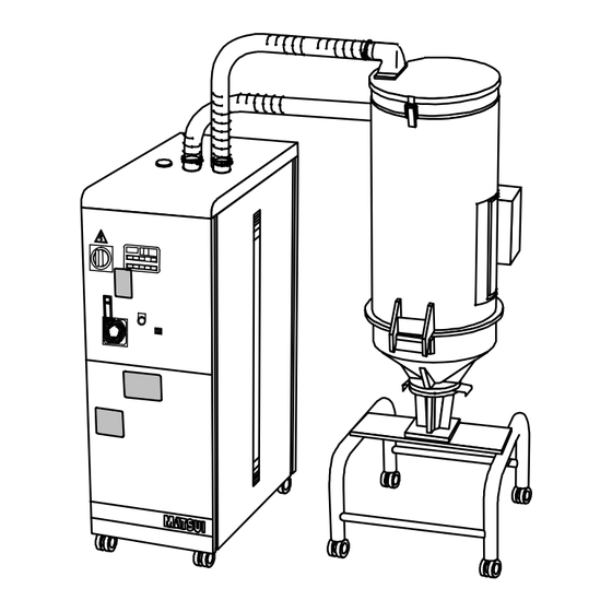
- Page 17 Chapter 2 Explanation Equipment <Dehumidifier> Connecting hose(heat resistant) Drying hopper Dehumidifying unit Frame Casters (4) Casters (4) Suction box (Shape depends on user’s specifications.) Picture 11 - 13 -...
- Page 18 Chapter 2 Explanation Equipment <The interior of the control panel> 1.DMS2-80,120/DMZ2-40 electromagn contactor fuse relay power breaker DC power capacitance thermal relay solid state relay terminal stand Picture 12 - 14 -...
- Page 19 Chapter 2 Explanation Equipment 2.DMS2-170,240 /DMZ2-80,120 relay electromagnetism contactor fuse DC power power breaker capacitance thermal relay terminal stand solid state relay Picture 13 - 15 -...
-
Page 20: Outer Dimensions
Chapter 2 Explanation Equipment 5. Outer dimensions (mm) Dehumidifying unit Drying hopper Picture 14 - 16 -... - Page 21 Chapter 2 Explanation Equipment Type Dehumidify DMS2-80,120/DMZ2-40 1410 1292 - - - - - unit DMS2-170,240/DMZ2-80,120 1410 1292 Drying hopper HD-10 HD-15 HD-25 1017 696 HD-50 1267 696 HD-75 1235 816 - - - - - - - HD-100 1435...
-
Page 22: Composition Flow Chart
Chapter 2 Explanation Equipment 6. Composition Flow Chart Basic composition flow chart for DMZ2 model is shown in following Figure 15. Picture 15 - 18 -... -
Page 23: Chapter 3 Installation
Chapter 3 Installation 1.The installation of the device (1)Dehumidifying unit drying funnel integrated stand type (Integrated dehumidifier) Step Item Task 1 ·Install on the levelly stable floor. Installation As shown in figure16, make sure the installation location gives space to perform maintenance. - Page 24 Chapter 3 Installation Step Item Task The confirmation of Please check before the main body of the integrated dehumidifier is the device state lifted. • Please make sure that no drying material is in the drying hopper. • Make sure if, shown as picture18, the catchclips(2piece) connected with the cylindrical section and conical section of drying hopper are whole sets.
- Page 25 Figure, be sure that eyebolts (4 pieces) fixed on the top are securely equipment screwed and then hook load lifting rope (with hooks) on them and lift and move dehumidifying dryer with using hoist at your company. <Only for DMS2-80,120/DMZ2-40type> Picture 20 - 21 -...
- Page 26 Chapter 3 Installation Step Item Task 4 Remove adhesive tape covering regeneration exhaust port as shown in Confirming Figure. dehumidifying unit condition Picture 21 - 22 -...
-
Page 27: Dehumidifying Unit Drying Funnel Separable Type
Chapter 3 Installation (2) Dehumidifying unit drying funnel separable type. Step Item Task 1 Install on the levelly stable floor. Installation As shown in figure22, make sure the installation location gives space to perform maintenance. 600mm 600mm 600mm 600mm Picture 22 Remove adhesive tape covering regeneration exhaust port as shown in Confirming Figure. - Page 28 Chapter 3 Installation Step Item Task Confirming Please check the following units before lift and move the dehumidifying dehumidifying unit unit main body. condition Please make sure that eyebolts (4 pieces) on the device are fastened as picture 24 shows. Bolts with holes (4 pieces) Picture 24 Make sure that the flat knob on the control board is installed.
- Page 29 Chapter 3 Installation Step Item Task 3 Moving the When lifting and moving dehumidifying dryer main body as shown in dehumidifying units Figure, be sure that hook load lifting rope (with hooks) to fasten the eyebolts (4 pieces)of the dehumidifying unit main body and lift and move dehumidifying dryer with using hoist at your company.
- Page 30 Chapter 3 Installation Step Item Task 4 Installing drying Install the base to fitting position on molder as shown in Figure. hopper base Fix it securely with 4 bolts. HD-10,15 type base HD-25~100 type base HD-150~300 type base picture 27 ※...
- Page 31 Chapter 3 Installation Step Item Task Confirming drying Please check before lifting and moving dehumidifying dryer main body. • Please make sure that no drying material is in the drying hopper. hopper condition • Be sure that catchclips (2 pieces) fastening drying hopper cylindrical section and base are securely set as shown in Figure28.
- Page 32 Chapter 3 Installation Step Item Task Confirming drying Be sure that adjusting fasteners (2 pieces) or handle (1 piece) fastening hopper condition cleaning door of drying hopper cylindrical section are securely set as shown in Figure. (Only for HD-75~300) Adjusting fasteners Picture 30 6...
- Page 33 Chapter 3 Installation Step Item Task Installing drying Install the main body to the base as shown in Figure. 【Caution!】 hopper ・Before installing main body, be sure that slide gate of the base is securely set. ・Fix the body with 4 bolts securely. HD-10,15 type base HD-25~100 type base HD-150~300 type base...
- Page 34 Chapter 3 Installation Step Item Task ※ Connecting the hose In case of circulation specifications, connec t dehumidifying unit and for connecting drying hopper with connecting hose (heat resisting hose) as shown in dehumidifying unit Figure. and drying hopper Heat resistant hose Hose clamp Connection...
- Page 35 Chapter 3 Installation (3) The common items of the integrated stand type and the separable type. Step Item Task Connecting Connect pipe or hose to water supply and drain ports of dehumidifying water supply unit as shown in Figure. <In case of connecting pipe> and drain hoses or pipes dehumidifying...
-
Page 36: The Connection Of The Power Supply
Connecting Connect relay cord of dehumidifying unit to relay box of drying hopper relay cord side. (Only for dehumidifying unit ,drying hopper separable type) Relay cord Relay box inside DMS2-80,120/DMZ2-40~120 DMS2-170,240 - K1 R 21 + K1 - K1 R 21 Picture 35 【Caution!】Be sure that it is fixed securely with machine screws and... - Page 37 Chapter 3 Installation Step Item Task Make sure that power breaker on control panel is turned “OFF” and Connecting power cord then connect power cord (5m) to power supply of the equipment at your company. R phase・・・・・ Red Power cord・・・S phase・・・・・ White・・・・For primary power supply T phase・・・・・...
-
Page 38: Inspecting Inside Of The Hopper
Chapter 4 Preparation for Operation Inspection Inside Drying Hopper (1)HD-10~50type Step Task As picture 36 shows, be sure that dismantle the U-type bolt which connects the cylindrical section and hot air pipe. U type bolt HD-10~50 Picture 36 As picture 37 shows, be sure that dismantle the catchclips (2 pieces) fastening drying hopper cylindrical section and base. - Page 39 Chapter 4 Preparation for Operation Step Task Hopper inside cleaning 【 Notice! 】 Do not impose extra strength on the cylindrical section more than necessary. Open the cylindrical section and check whether there is foreign particle in. Packing a Packing b Diffuser Separator Picture 38...
- Page 40 Chapter 4 Preparation for Operation Step Task After inspection and cleaning of inside, fix the removed parts again Packing fixing part Packing Please set the packing the groove as shown in figure. Packing Diffuser fixing part Separator packing fixing part Diffuser ※Please set the separator and ※Please fix diffuser with the...
- Page 41 Chapter 4 Preparation for Operation (2)HD-75~300 type Step Item Remove adjusting fastener or handle shown in Figure and open cleaning door to confirm there is no foreign matter inside of it. Single type Heat retaining type (double) djusting fastener Handle Picture 41 In order to keep clean, to take out parts and then clean the hopper inside and the extracted parts with compressed air or gauze.
- Page 42 Chapter 4 Preparation for Operation Step Item ( In case of HD-150,200) Inner sruface cleaning Hot air pipe Diffuser Inner and outer surface cleaning ※Remove diffuser by moving it up and down or rotating it along groove of hot air pipe. Picture 43 (...
- Page 43 Chapter 4 Preparation for Operation Step Item After inspection and cleaning of inside, fix the removed parts again and close cleaning door and set adjusting fastener or handle securely. ※Fix lid securely with In case of catchclip. HD-75~200 Catchclip HD-75,100 Diffuser fitting part HD-150~300 Diffuser fitting part Set pin Hot air pipe...
-
Page 44: Condition Confirmation Of Each Unit And Feeding Of The Resin
Chapter 4 Preparation for Operation 2. Condition Check of Each Unit and Loading of Resin Apparatus Machine confirmation and content Please set the filter surely with catchclip.especially,make sure Drying filter “A ”part not to shift . Tighten up a lid fast for there not to be air leak. Drying filter Section figure Filter case... - Page 45 Chapter 4 Preparation for Operation Apparatus Machine confirmation and content Regeneration filter Confirm that the filter is set surely as the figure. Use the fingers to chinch the part and conduct installation and dismantle Regeneration filter Filter stopper Picture 47 Confirm whether or not each hose is connected as in the Hose installation point.
- Page 46 Chapter 4 Preparation for Operation Apparatus Machine confirmation and content Regenerative temperature Regenerative temperature setter be set up at the time of setter shipment already. Picture 49 Slide gate Material outlet Be sure that slide gate and material outlet at the lower part of drying hopper are closed securely as shown in Figure 50 and then load material into drying hopper.
-
Page 47: Operating Procedures
Chapter 5 Operation Procedures Step Operation Details Power ON Set the power breaker in front to “ON”. Preparations for Press the CONTROL ON in the front. switch operation The display of the controller lights up. Drying start-up When pressing Dryer switch, the『Dryer』 indicator lights up and the dry operation starts. - Page 48 Chapter 6 Maintenance High Temperature Caution After the unit operation stops, for a while, the hot condition continues. Wait for maintenance and inspection until the unit gets cold (5 h are a standard in the nature cooling). And, even if the outside of the unit is cold, be careful sufficiently because the inside and the dry material sometimes are in hot condition.
- Page 49 Chapter 6 Maintenance Maintenance item Description Confirmation of Confirm whether the dry temperature and regeneration temperature are controlled at the setting temperature of controller. temperature <Confirming method> 【In case of dry temperature】 1. After pushing the SV switch of the controller once, do the『SV』 indicator light up and confirm a setting value with dry temperature.
- Page 50 Chapter 6 Maintenance 2. Weekly maintenance Maintenance item Description Removing and air leak of Hose connecting dehumidifying unit and drying hopper hose (heat resistant hose) Check hoses between dehumidifying unit and drying hopper are not disconnected and check there is no air leak as shown in Figure. Hose picture 52 ※...
- Page 51 Chapter 6 Maintenance Maintenance item Description (Dry filter) Filter cleaning Removing a filter case of dehumidifying unit , check and clean up the filter clogging as shown in Figure53. Dry filter Catchclips ( ) 3 pieces picture 53 (Regeneration filter) In case of DMS2-120,170,240 Removing a filter stopper...
- Page 52 Chapter 6 Maintenance 3.Monthly maintenance Maintenance item Description Confirm the loosening of the wiring connection part of the electronics Rising fastens for equipment inside the control panel and in the unit. And, perform the the terminal rising fastens in the connection part. CAUTION The check is after stop the unit, always, perform after turned “OFF”...
- Page 53 Chapter 6 Maintenance 5. Every six months maintenance Maintenance item Description Check about whether there is not loosening of bolt and Nut at Bolt and Nut each part of the unit. Then, perform rising fastens. in each unit part Rotor belt, Tension of Check for any cracks, broken portion and tightness on the belt Spring plate and confirm the belt in case of any unusual function.
- Page 54 Chapter 7 Alarms Function CAUTION Before doing the check of the malfunction cause and recovery, always perform the power breaker of control panel “OFF”. The work with power “ON”, causes the trouble and the accident. Don't do absolutely. When the malfunction occurs during operation of the equipment, the protection unit operates, the alarm character is displayed in the control panel and the alarm buzzer sounds and informs the malfunction.
- Page 55 Chapter 7 Alarms Function Alarm Character Malfunction contents/Interlock Measure indicator indicator When wiring for the Refer to CHAPTER 8. Regeneration thermocouple (CA sensor) Troubleshooting and restore sensor and the thermocouple for the extraordinary occurrence broken dryness are broken. cause. ↓ The operation stops When pushing a Reset switch automatically.
- Page 56 Chapter 8 Troubleshooting 【Notice!】Before check Set the switch『Run-Stop』to『Stop』,Check after making a breaker “OFF”, the confirmation in the full stop of the equipment and heating part temperature's falling to the temperature that doesn't get a burn. Specified about the malfunction of the following of this chapter. Carrying Malfunction part Contents...
- Page 57 Chapter 8 Troubleshooting The dry blower does not rotate. Check point Action Remarks Confirm whether or not the When the following disposal Set the primary power and the indicator of the controller doesn't correct dispose by page front power breaker in 59;...
- Page 58 For purchase and type of the cartridge filter, contact your nearest MATSUI BRANCH or distributor. Take out the regeneration If it is dirty or clogged, blow If deterioration of the cartridge filter, and check it for clogging.
- Page 59 For purchase and type of the cartridge filter, contact your nearest MATSUI BRANCH or distributor. Dismount the regeneration If it is dirty or clogged, blow If deterioration of the cartridge filter, and check the filter for...
- Page 60 For replacement, contact your (MC-0) magnet contacts for nearest MATSUI BRANCH or adhesion and check to see if distributor. the magnets perform opening People not having sufficient and closing operations when knowledge of electricity will the power is on.
- Page 61 (MC-1~MC-4) normal operations, replace it. For replacement, contact your magnet contacts for adhesion nearest MATSUI BRANCH or and check to see if the distributor. magnets perform opening and People not having sufficient closing operations when the knowledge of electricity will power is on.
- Page 62 Chapter 8 Troubleshooting The moisture content of resin does not decrease. Check point Action Remarks Check the cooling water flow When cooling water isn't and water volume lack. flowing, confirm the open condition of each valve. Take the cartridge filter out of If it is dirty or clogged, blow If deterioration of the cartridge the line filter case, and check it...
- Page 63 Chapter 8 Troubleshooting The indicator with the PV value of the controller doesn't display the condition of “ON” in primary power and pushes the CONTROL ON switch. Check point Action Remarks When not becoming “ON”, Check whether or not the front power breaker of the control perform the power breaker "ON"...
- Page 64 Chapter 8 Troubleshooting The thermal setting value of every model (A) OCR-1 Power Type Setting current(A) 50Hz 60Hz AC200V~ 4.3~4.8 5~4.54 DMS2-80 AC220V 4.3~4.8 5~4.54 DMS2-120 7.44~8.76 8.2~7.3 DMS2-170 10.8~10.9 11.7~10.3 DMS2-240 1.72~2.41 1.93~1.93 DMZ2-40 4.3~4.8 5~4.54 DMZ2-80 7.44~8.76 8.2~7.3 DMZ2-120 AC380~...
-
Page 65: The Shipment Setting Value For The Controller
Chapter 9 Technical manual 1. The shipment setting value for the controller Note ※1 Must be set when assemble the transportation equipment. It may be ignored in standard condition. The parameter for the user setting mode Of pushing SV switch every, the parameter indicator switches over. But when pushing SV switch more than 5 seconds, changes to the engineering setting mode. -
Page 66: The Start-Up Method For The Auto Tuning
Chapter 9 Technical manual 2. The start-up method for the auto tuning ① During the dry unit operating, starts the auto tuning when push continuing △ and ▽ key at the same time for 2 seconds during display of the dry temperature measurement value. (During auto tuning, displays alternately at the period in 1 second in the measurement temperature and「At」) ②... -
Page 67: Consumable Parts List
Chapter 10 Consumable Parts List 【Machine parts】 Type Title and Type DMZ2-40/ DMS2-80,120 DMZ2-80,120/ DMS2-170,240 PS/150 Regenerative filter φ150×t10 DMSφ200×250 - Two sides Drying filter DMSφ200×350 - Two sides - 345L100 Rotating machine Drive tape - 367L100 【Electric parts】 Electromagnetism... -
Page 68: Dehumidifying Rotor Specifications
Chapter 11 Specifications 1.Dehumidifying rotor specifications Type DMS2- ℃ Drying air -20(According the change of using condition) average dew Temperature30℃,relative humidity75%(DP+25℃),infusing External condition point external air10% Drying wind quantity ℃ Drying 80~130(180) temperature Drying blower Parameter RB40-520 RB50-520 RB60-520 Designed wind quantity /min) Output of electric motor (Kw) 0.9/1.15... - Page 69 Chapter 11 Specifications Type DMS2- Control Drying temperature adjustment PID control Regeneration temperature PID control adjustment Set up times (10minute~99hour50minute) Out automatic start timer Alarm protection loop Over-temperature (drying regeneration) Motor over-load (Drying)(Drying regeneration) Running prevention Cooling delay when stopping AC200V 50/60Hz,220V 60Hz,380V 50/60Hz,415V Power supply 50/60Hz 3P...
- Page 70 Chapter 11 Specifications Type DMZ2- ℃ -40(according the change of using condition) Drying air average dew Temperature30℃,relative humidity75%(DP+25℃), External condition point infusing external air10% Drying wind quantity Drying ℃ 80~130(180) temperature Drying blower Parameter 50/60Hz RB30-520 RB40-520 RB50-520 Output of electric motor Kw 0.38/0.42 0.9/1.15 1.5/1.75...
- Page 71 Chapter 11 Specifications Type DMZ2- Drying temperature Control PID control adjustment Regeneration temperature PID control adjustment Set up times (10minute~99hour50minute) Out automatic start timer Alarm protection loop Over-temperature (drying regeneration) Motor over-load Running prevention Cooling delay when stopping Power supply AC200V 50/60Hz,220V 60Hz,380V 50/60Hz,415V 50/60Hz 3P Operation circuit voltage...
-
Page 72: Drying Hopper Specifications
Chapter 11 Specifications 2.Dying Hopper Instruction Type HD-10 HD-15 Standard ℃ 130(Max.) Drying High temperature ℃ 180(Max) temperature Standard Kw ※1 High temperature Kw Heater capacity Effective volume Quality of material SUS304 Width mm Size Depth mm Height mm Type HD-25 HD-50 HD-75... - Page 73 Chapter 12 Optional parts Type General purpose type Control panel Selection item (Standard) ─ Communication function (RS-232C) ○ Material-reducing alarm ─ Filter-jammed alarming ─ Resin temperature display ○ Calendar timer ○ External start signal ○ Alarm ○ Dew point gauge(-90℃~+10℃) - 69 -...
-
Page 74: Circuit Diagrams・Electric Parts Table
Appendix 1.Circuit diagrams DMS2-80,120,170,240 ELB-1 V 50/60Hz ¦ Υ 3 RVV 6mm (80~120) RVV 10mm RVV 16mm (170) (240) NFB-1 RV 6mm (80~170) RV 10mm (240) MS-1 OCR-1 2.0sq 2.0sq Drying blower 2.0sq 2.0sq 200~240V △ Method 380~440V Y Method 2.0sq... - Page 75 Appendix DMZ2-40,80,120 PE L1 L2 L3 (E) (R) (S) ELB-1 V 50/60Hz φ3 RVV 4mm (40) RVV 6mm (80) RVV 10mm (120) NFB-1 RV 4mm (40,80) RV 6mm (120) MS-1 OCR-1 2.0sq 2.0sq Drying blower 2.0sq 2.0sq 200 ~ 240V △...
- Page 76 Drying Reg. Rotate Reg.heater Drying heater 460V blower blower blower 50Hz 60Hz 50/60Hz 50/60Hz Standard High temp. NO.2 NO.2 NO.1 NO.1 DMS2-80 2.67 1.15 2.67 65/60(W) DMS2-120 1.15 DMZ2-40 2.67 0.38 0.42 15(W) DMS2-170 1.75 DMS2-240 5.49 2.25 85/110(W) DMZ2-80 1.15...
- Page 77 Appendix DMS2-80,120,170,240 TC-1 TC-1 Indicator pannel Control pannel Dry sensor Reg.sensor OCR-1 Drying blower OCR-3 NO.1 Level switch Feeding blower SOL-1 NO.1 Discharge valve Branch valve 1 NO.2 Level switch SOL-2 NO.3 Level switch SOL-3 Branch valve 2 SOL-4 Branch valve 3...
- Page 78 Appendix DMZ2-40,80,120 TC-1 TC-1 Indicator pannel Control pannel Dry sensor Reg.sensor OCR-1 Drying blower OCR-3 NO.1 Level switch Feeding blower SOL-1 NO.1 Discharge valve NO.2 Level switch SOL-2 Branch valve 1 NO.3 Level switch Branch valve 2 SOL-3 Branch valve 3 SOL-4 OCR-1 SOL-5...
- Page 79 Appendix NO.1 Direction Level switch control Photo electricity switch control Limit switch control Capacity approximate switch control Blue Brown LS-1 Blue Brown LV-1 LV-1 LV-1B (N/O) (1) (N/O) Black LV-1A Blue Brown (N/O) (N/O) Black NO.2 Direction Limit switch control Capacity approximate switch control Photo electricity switch control Level switch control...
- Page 80 Appendix Electric parts table Marker:50Hz/60Hz (High temperature) φ3 Type:DMS2-80,120,170,240 A Code Name Specifications Number Remark NF63-CW 3P 10A(16A) (80) NF63-CW 3P 16A(20A) (120) MITSUBISHI 380V/415V NF63-CW 3P 20A(32A) (170) NF63-CW 3P 32A(40A) (240) NFB-1 Breaker NF63-CW 3P 20A(32A) (80) NF63-CW 3P 32A(40A) (120)
- Page 81 Appendix Marker:50Hz/60Hz (High temperature) φ3 Type:DMS2-80,120,170,240 A Numbe Code Name Specifications Remark TR-ON/3(2.2-3.4A)(80,120) FUJI TR-ON/3 (4-6A) (170) 380V/415V TR-ON/3 (5-8A) (240) OCR-1 Thermal relay TR-ON/3 (4-6A) (80,120) FUJI TR-ON/3 (6-9A) (170) 200V/220V TR-5-1N/3 (9-13A) (240) Auxiliary contact SZ-A20 FUJI FUJI...
- Page 82 Appendix Marker:50Hz/60Hz (High temperature) φ3 Type:DMS2-80,120,170,240 A Code Name Specifications Number Remark That is electric component correspond to special demand OP-1-1 Weekly Timer TR-1 H5S-WA2 (OMRON) Weekly Timer OP-1-2 Select switch T2SSR1B-1a (TaiwanTianDe) Weekly Timer OP-2-1 (Q.Light) S100-UA AC200V PL-AL...
- Page 83 Appendix Marker: 50Hz/60Hz (High temperature) φ3 Type:DMZ2-40,80,120A Code Name Specifications Number Remark NF63-CW 3P 10A(16A)(40) MITSUBISHI NF63-CW 3P 16A(20A)(80) 380V/415V NF63-CW 3P 20A(32A)(120) NFB-1 Breaker NF63-CW 3P 20A (40) MITSUBISHI NF63-CW 3P 32A(40A)(80) 200V/220V NF63-CW 3P 40A(50A)(120) Terminal Cap TCS-05SW3W MITSUBISHI Red/Yellow for V Operation Hander...
- Page 84 Appendix Marker: 50Hz/60Hz (High temperature) φ3 Type:DMZ2-40,80,120A Code Name Specifications Number Remark T-35K Type φ3.2×70 (+15) ×1.5A Thermocouple Shanghai Hongduan TC-1 Contactor G2422 1set TOHO Metal connective BVH-21T-P1.1 (JST) TOHO terminal Metal connective BXH-001T-P0.6 (JST) TOHO terminal Buzzer EA4202 AC200V Panasonic PB-1 Button...
Need help?
Do you have a question about the DMS2-80 and is the answer not in the manual?
Questions and answers