
Subscribe to Our Youtube Channel
Summary of Contents for Beretta POWER PLUS BOX INT
- Page 1 Installation Manual Power Plus Box INT-EXT THERMAL MODULES | CONDENSING Installation Manual...
- Page 2 POWER PLUS BOX 200 M P INT 20074455 choice of product. POWER PLUS BOX 150 M V INT 20074457 Beretta POWER PLUS BOX 200 M V INT 20074459 POWER PLUS BOX 250 M P EXT 20074447 POWER PLUS BOX 300 M P EXT...
-
Page 3: Table Of Contents
CONTENTS GENERAL INFORMATION ....4 COMMISSIONING AND MAINTENANCE..34 General Safety Information ....4 Initial startup . -
Page 4: General Information
GENERAL INFORMATION 1.2 Precautions The operation of any appliance that uses fuel, electrical power and water demands that a number of fundamental 1.1 General Safety Information safety precautions be respected: Do not allow children or infirm persons to operate the After removing the packaging, check the condition system unsupervised. -
Page 5: Safety Devices
Depending on the model, the heat input (ref. PCI) of every Power Plus Box 200 EXT modular system reaches 110, 135 or 180 kW, and can be Base module consisting of 4 heat generators for heating modulated between 10% and 100%. and DHW production systems. -
Page 6: Identification
The modular system must not be operated, even temporarily, if the safety devices are not functioning or have been tampered with. The safety devices must be replaced by Technical Assistance Centre, only using original components from the manufacturer. Refer to the spare parts catalogue provided with the modular system. -
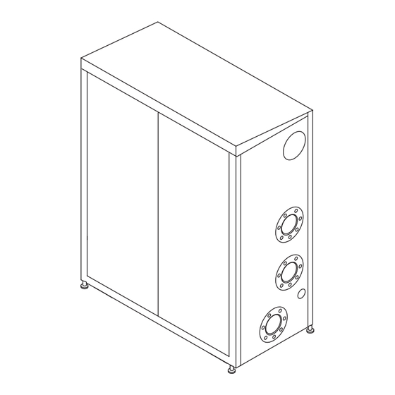
Page 7: System Layout
1.6 System layout Control panel Single heating element Control panel Bus cable passage cable gland for the cascade connection Flue gas manifold Gas manifold System delivery manifold Condensate drain manifold System return manifold Single heating element flue gas analysis outlet Single heating element flue gas exhaust union Automatic bleed valve Safety thermostat... -
Page 8: Coupling Configuration
COMPENSATORE POWER PLUS BOX 200 IDRAULICO 80°C 60°C 50°C 30°C COMPENSATORE POWER PLUS BOX 150 POWER PLUS BOX 200 IDRAULICO Delivery manifold sensor Low system temperature sensor Boiler sensor Outdoor sensor Zone 1 circulator (high temperature) Zone 2 circulator (low temperature) Boiler circulator Mixer valve NOTE: it is possible to couple up to a maximum of 4... -
Page 9: Technical Specifications
Power Plus Box MODEL 115 HI Fuel G20 - G30 - G31 Device category II2H3+ Device type B23, B53 Furnace heat output ref. PCS (min - max) 16,0 - 127,9 16,0 - 150 16,0 - 200 Furnace heat output ref. PCI (min - max) 14,4 - 115 14,4 - 134,9 14,4 - 179,8... - Page 10 Power Plus Box Detail 115 HI Maximum rated heat input Minimum rated heat input 16,7 16,7 16,7 Domestic hot water maximum rated thermal input (80-60) Domestic hot water minimum rated thermal input (80-60) PARAMETER Seasonal heating energy efficiency class Water heating energy efficiency class Rated input Prated 88,4...
-
Page 11: Water Circuit
1.9 Water circuit Safety valve Automatic bleed valve Air inlet Burner Exhaust flue duct Heat exchanger Condensate outlet Drain cock Central heating flow Differential water and minimum pressure switch Central heating return Circulator (or 2-way valve) Gas supply Gas valve Flue gas exhaust union with check valve and flue gas analysis outlet Manual diverting valve... - Page 12 WATER SIDE PRESSURE DROP FOR EVERY HEATING ELEMENT Every heating element of the modular system is equipped with a circulator, whose performance curve is Power Plus Box provided below, in reference to speed 3. 1200 1 heating element 1100 1000 Circulator characteristic curve P available for...
-
Page 13: Location Of Sensors
1.10 Location of sensors Delivery manifold sensor Low system temperature sensor Boiler sensor Outdoor sensor Zone 1 circulator (high temperature) SAFETY Zone 2 circulator (low temperature) HEATING THERMOSTAT DELIVERY SENSOR Boiler circulator (triggering at 90°C) Mixer valve HEATING RETURN SENSOR 80°C FLUE GAS 60°C... -
Page 14: Wiring Diagrams
Ground star pole Ground star pole Connection by the installer Terra 230V~50Hz Neutro Fase J10 6 J11 7 al polo stella di terra Pump J10 5 J11 14 EA/ER J10 4 J11 6 Pump J10 3 J11 13 Terra Terra J10 2 J11 5 Pump 3... - Page 15 al polo stella di terra al polo stella di terra al polo stella di terra EA/ER EA/ER EA/ER Terra Terra Terra Terra Terra Terra Fusibile 4A Terra Fusibile 4A Terra Fusibile 4A Terra Fase Fase Fase Neutro Neutro Neutro Circolatore Circolatore Circolatore Valvola gas...
-
Page 16: Control Panels
1.12 Control panels 4 5 6 4 5 6 4 5 6 14 15 Electric power supply signal Display Master user interface Value increase button Slave user interface Value decrease button Slave card operating status signal: Save button - FLASHES in absence of heat demand Parameter selection button - FLASHES QUICKLY during the ignition cycle Operating mode selection button... -
Page 17: User Interface (Master)
Functional notes - The exhaust function: the high and low temperature modular system control panel manages: circuit pumps remain in operation for 5 minutes after Power Plus Box - The DHW priority function which, in the case of a the last burner is turned off. The waiting time before DHW demand, the master card can also serve the the heating element circulator is stopped once the high or low temperature circuit. -
Page 18: Display Mode
1.13.1 Display mode The red (error) LED turns on in the case of faults that involve the permanent block of a heating element (normal operation can be reset by pressing the Master or Slave reset button). The green (on) LED indicates the presence of the electric power supply. The 3 digits with seven segments display the system statuses: SYSTEM STATUS DISPLAY... -
Page 19: Changing The User Parameters
1.13.3 Changing the user parameters Pressing displays the following values in succession: - manifold delivery temperature T1 - DHW temperature T3 - low temperature circuit delivery temperature T6. To change the relative setpoints: - press the button: the relative value will appear, the two digits on the right will flash "Set/esc"... -
Page 20: Installer Programming Mode
The following values for each single unit can be visualized with POS. DIMENSIONS DISPLAY Flow temperature (e.g. 70° C) Return temperature (e.g. 50° C) Exhaust flue temperature (e.g. 60° C) Ionization current (index from 0 to 99). E.g. fig. Ionization current index 44. Fan PWM signal (%). -
Page 21: Test Mode
1.13.6 Test mode In test mode it is possible to generate a high temperature heating demand at maximum power and at minimum power. All system fans must be activated. If the installer turns off the switch for some Slaves, the others, connected to the Master, must continue to operate. -
Page 22: Installation
INSTALLATION 2.2 Opening Remove the straps (1) and the cardboard packaging (2). 2.1 Unpacking the product 1 Strap 2 Cardboard packaging Power Plus Box condensing system is supplied on a 3 Pallet pallet, strapped and protected by cardboard packaging. 4 Modular condensing system Its condition and compliance with what was ordered must 5 Document envelope containing: be checked immediately. -
Page 23: Overall Dimensions And Weights
2.3 Overall dimensions and weights 1250 Power Plus Box DESCRIPTION 115 HI System delivery manifold 5" DN 125 - PN 6 Ø - DN System return manifold 5" DN 125 - PN 6 Ø - DN Gas manifold 3" DN 80 - PN 6 Ø... -
Page 24: Handling
The packaging material must be disposed of carefully 2.4 Handling and must not be abandoned, as it is a source of A transpallet or forklift must be used for handling. potential danger. 2.5 Installation premises Power Plus Box systems (models ) are designed for outdoor installation. -
Page 25: Water Connections
- Make sure that the electrical supply system has been installed by a qualified electrician in compliance with applicable standards - Make sure that the flow rate, head and direction of flow of the pumps are suitable and correct - Make sure that the fuel feed line and any storage tank are made and installed in compliance with applicable standards - Make sure that expansion vessels are big enough to... -
Page 26: Flue Gas Evacuation For Installations In A Central Heating Plant
2.8 Flue gas evacuation for installations in a central heating plant When constructing evacuation lines for installations in a central heating plant, materials must be used that are resistant to products of combustion (temperature between 40 °C and 100 °C, relative humidity also above 100%), in class W1 according to UNI EN 1443, typically stainless steel or plastic materials. -
Page 27: Condensate Evacuation
Any condensate neutralisation devices can be 2.9 Condensate evacuation connected after the siphon. For the calculation of Power Plus Box condensation systems produce a the duration of the neutralisation load, the amount of condensate flow depending on the operating conditions. neutraliser consumption must be evaluated after one The maximum hourly flow of condensation produced is year of operation. -
Page 28: Electrical Connections
Maintenance Neutralisation device maintenance must be performed at regular intervals and as required (minimum once per year). The requirement for maintenance depends on the system characteristics. For this purpose, the filling level of the dolomitic granules must be checked. The minimum filling level is equal to 15 cm, starting from the upper edge of the box. - Page 29 ROTATE ROTATE identify the cable glands (5) located on the rear part of the modular system and use them to pass the pump, sensor and electric power supply cables inside the modular system - Identify the terminal board (6), located inside the electric panel, and direct the pump and sensor cables (7) towards it through the holes made in the panel casing.
- Page 30 TERMINAL BOARD INSIDE THE CONTROL PANEL Pump PB (*) High temperature DHW circulator zone 1 sensor Pump PZ1 (*) System circulator Boiler sensor High temperature Pump 3 PZ2 (*) System circulator Low temperature Low temperature zone 2 sensor Circ. 2 Valv.
-
Page 31: Outdoor Sensor Installation
2.12 Outdoor sensor installation The correct positioning of the outdoor sensor is of fundamental importance for proper climate control operation. The sensor must be installed outside the building to be heated, at approx. 2/3 the height of the NORTH or NORTH WEST façade and far from flues, doors, windows and sunny areas. -
Page 32: System Filling And Emptying
- Open the filling tap (4), provided on the system, until 2.13 the pressure indicated on the pressure gauge is Power Plus Box filling system is not equipped with a filling tap, which must be installed on the system return. - Close the filling tap (4). -
Page 33: Preparing For Initial Startup
EMPTYING THE HEATING ELEMENT - the hydraulic circuit pressure, when cold, is approx. - Close the diverting valve (1) and the return tap (2) for and the circuit has been deaerated 1.5 bar the heating element - connect a plastic pipe to the heating element's drain tap (5) and open it Before opening the drain tap (5) protect the underlying electric devices from the existing water... -
Page 34: Commissioning And Maintenance
COMMISSIONING AND MAINTENANCE 3.1 Initial startup - Turn the main system switch "on" - press the button: the manifold delivery temperature will be displayed, preceded by the symbol “1” - press “Set/esc” : the relative setpoint is displayed and the two digits to the right will flash. To change this value press . -
Page 35: Checks During And After Initial Start-Up
In the case of low temperature systems, select a temperature between 20°C and 45°C. By setting the "low temperature" type system, the maximum delivery temperature setting will be limited to 50°C (Par. 23=T_CH_Low_limit). Changing the delivery temperature involves changing the climatic curve (see the “Heat control setting”). This change may only be made by Technical Assistance Centre. - Page 36 Check that the modular system stops completely when turning the main system switch to "off". Electrically power the modular system by turning the main system switch and the main device switch to "on". - generate the heat demand using the room thermostat. The system will operate at maximum power, indicating “H”...
-
Page 37: Adjusting The Functional Parameters
- generate the heat demand using the room thermostat. 3.3 Adjusting the functional The system will operate at maximum power, parameters indicating “H” on the display followed by the delivery temperature (flue cleaning function) The heating functions can be set for the high temperature, - combustion can be checked by unscrewing the cap low temperature and DHW circuits based on the system (4) and inserting the analyser sensor in the foreseen... -
Page 38: Setting The Heating Parameters
3.4 Setting the heating parameters The following heating parameters can be set: Setpoint_T_CH_High High temperature circuit setpoint (parameter 1) If the "fixed point" operating mode is set (par. 14=CH_type_high=0), it is the target temperature. If the "climatic control" operating mode is set (par. 14=1) , it is the maximum target temperature with minimum outdoor temperature (T_out_min=par. -
Page 39: Setting The Dhw Parameters
CH_Priority 3.6 Heat control setting Heating priority (parameter 16) Attenuation_High If set to 0, the system will work without heating priority with HIGH TEMPERATURE circuit attenuation function the high temperature and low temperature circuits served (parameter 21) in parallel. There are 2 cases: If set to 1, the demand from the low temperature circuit - Fixed point operation Par. - Page 40 If the outdoor temperature = Tout_min=Par. 37, preset to If the outdoor temperature = Tout_min=Par. 37, preset to 0°C, 0°C, then setpoint =setpoint_T_Ch_high. then setpoint =setpoint_T_Ch_low. If the outdoor temperature = Tout_max=Par. 38, preset to If the outdoor temperature = Tout_max=Par. 38, preset to 18°C, 18°C, then setpoint T_ch_high_ foot=Par.
- Page 41 MODE: MINIMUM QUANTITY OF BURNERS IGNITED Low load (PAR. 33=0) The low load function prevents burner ignition and shut off System power modulation is controlled by a PID regulator, in the case of a low heat demand. The conditions for low which controls the manifold temperature and the setpoint load operation activation is controlled in every Slave card is that of the active circuit (high or low temperature circuit...
- Page 42 The burner shuts off when: - Delivery temp. > Setpoint_ch_high (Par.1) + Ch_ high_hist_off (Par.20) - (Delivery temp. > Setpoint_ch_low (Par.3) + Ch_low_ hist_off (Par.27)) MIX VALVE MANAGEMENT The mix valve is controlled by the parameters: - Mix_valve_step_open_time: Par.28 preset to 5s - Mix_valve_step_close_time: Par.29 preset to 7s - Mix_valve_interval_time: Par.30 preset to 5s - Mix_valve_p_hyst: Par.31 preset to 2°C...
-
Page 43: Setting Addresses For Cascade Coupling
Safety functions of the Slave cards Checking T uses the parameter T_max (preset to 35°C) If the delivery temperature > 90°C for 5s, the slave card is and limits the burner power as follows: blocked (no. 46). - if T_max -5°C > T >... - Page 44 Example of a cascading configuration with 1 system 200 and 1 Power Plus Box Power Plus Box In this case, there are two blocks: the first consisting of four generators and the third of three. Therefore, two blocks must be configured, respectively with addresses 1 and 2. The slave addresses (J10) must not be changed. FIRST modular system SECOND modular system POWER PLUS BOX 200...
-
Page 45: Error List
3.8 Error List A and E type errors possibly encountered with Power Plus Box are given in the tables below. In this sense it should be specified that an E-type error (volatile error) is a fault which automatically disappears as soon as the fault is resolved;... - Page 46 No. on the PC Cause Troubleshooting Internal error Replace the Slave card. Internal software error Press the rest button. Internal error Replace the Slave card. The limit thermostat contact is Connector disconnected or defective. open with the burner off Limit thermostat defective. Delivery sensor error due to Check that the flow rate in each unit’s water circuit is exceeding the limit temp.
-
Page 47: List Of Parameters
3.9 List of parameters The list of parameters for Power Plus Box is given here below. The user may only alter the first three parameters, whilst Technical Assistance Centre must be called in for the others. User parameters Factory Lower Upper Parameter name Description... - Page 48 Factory Lower Upper Parameter name Description setting limit limit CH1 max. Temp. 80°C 10°C 80°C Max. settable value for high system CH1 min. Temp. 50°C 10°C Par.1 Min temp. value high system (at max. external T.). Burner re-ignites after said differential. CH1 ON diff.
-
Page 49: Transformation From One Gas Type To Another
3.10 Transformation from one gas 6.75 type to another system is supplied for operating Power Plus Box with G20 (natural gas). It can however be transformed to operate with G30-G31 (LPG) using the provided kit. The transformations may only be carried out by Technical Assistance Centre or by personnel authorised by , also on already installed... -
Page 50: Temporary Shutdown
CO2 ADJUSTMENT AT MAXIMUM POWER With the electric power supply remaining active, as - Press the buttons at the same time signalled by the flashing green LED and the supply of the “Set/esc” for 5 seconds gas, the modular system is protected. - use to select the maximum fan speed - generate the heat demand using the room thermostat. -
Page 51: Maintenance
Access to the control panel and the internal modular 3.14 Maintenance system parts Period maintenance is "mandatory', required by Presidential - open the two front doors in the casing Degree 26 August 1993 no. 412, and is also essential for - loosen the screw (1) and turn the main control panel device safety, efficiency and duration It makes it possible to reduce consumption, polluting emissions and keep the... - Page 52 Pump Pump Pump 3 Circ. 2 Valv.Mix Alarm Analogic Input Circ.2 Once the maintenance operations are complete, refit the Once the maintenance operations are complete, refit the components working in the opposite direction of what was components working in the opposite direction of what was described.
- Page 53 Disassembling and cleaning the burner and exchanger Disassembling the doors - open the two front doors in the casing In particular operations must be carried out inside the - disconnect the wiring (16) of the fan (17) modular system, the two front doors can be disassembled. - unscrew the two screws (19) that fix the fan (17) to the Proceed as follows: air conveyor (20)
-
Page 54: Troubleshooting
3.16 Troubleshooting FAULT CAUSE SOLUTION - Check the seal of the gaskets and There is a smell of gas Gas supply circuit. the closure of the pressure tapping points - Check the gasket seals Odour of unburnt gas Flue gas circuit - Make sure there are no obstructions - Check the combustion quality Burner gas pressure... - Page 55 FAULT CAUSE SOLUTION - Check/unseize the pump - Replace the circulator. The circulator does not start Pump malfunctioning - Check the electrical connection of the circulator System safety valve - Check calibration or efficiency - Check the circuit pressure Frequent tripping of the system System circuit pressure safety valve - Check pressure reducer functioning...
-
Page 56: Water In Central Heating Systems
General note on water used to top up systems: WATER IN CENTRAL HEATING - If softened water is used to top up a system, 8 weeks SYSTEMS of functioning after topping up, verify that the water in the system respects the above limits, in particular for INTRODUCTION electrical conductivity. - Page 57 3.2 Stray current corrosion Corrosion from stray currents can occur due to the differing electrical potentials between water in the boiler and the metallic mass of the boiler or piping. This process leaves unmistakeable traces i.e. small regular conical holes. All metallic parts should be grounded by an efficient earth cable for this reason.
- Page 58 The safety valve with the CE marking according to directive 97/23/ EC will be installed directly on each module by the manufacturer on the delivery manifold and therefore does not require any additional safety valve downstream of the last module. Beretta...
- Page 60 Commercial Of ces: Via Risorgimento, 23 A 23900 - Lecco www.berettaboilers.com Beretta reserves the right to modify the characteristics and speci cations given in this publication at any time and without prior notice as part of its policy of continuous product improvement.
Need help?
Do you have a question about the POWER PLUS BOX INT and is the answer not in the manual?
Questions and answers