
Subscribe to Our Youtube Channel
Summary of Contents for Paradigm 100
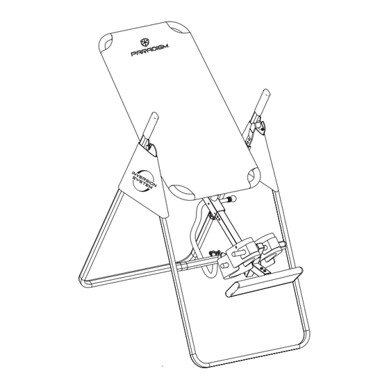
- Page 1 PARADIGM 100 INVERSION TABLE OWNER’S MANUAL ITEML#5206 The specifications of this product may vary from this photo, subject to change without notice.
- Page 2 *If the product has major defects which prevent it from functioning properly, please return it to the store of purchase within the period allowed by the store. Paradigm Health & Wellness, Inc. 1189 Jellick Ave. City of Industry, CA 91748, USA...
-
Page 3: Table Of Contents
TABLE OF CONTENTS Placement of Warning Labels WARNING: Before beginning Safety Precautions this or any exercise program. Overview Drawing Consult your physician, this is Parts List especially important for people Hardware Packing List with pre-existing health problems. Assembly Instructions Safety Operating NOTE: Maximum Weight Instructions Capacity for this product is... -
Page 5: Safety Precautions
SAFETY PRECAUTIONS This inversion table was designed and built for optimum safety. However, certain precautions apply whenever you operate the exercise equipment. Be sure to read the entire manual before assembling and operating this equipment. Also, please note the following safety instructions: 1. -
Page 7: Overview Drawing
OVERVIEW DRAWING... -
Page 8: Parts List
PARTS LIST Part # Description Quantity Part # Description Quantity Front U-Frame Washer Ø 16 *Ø 6.5 * 1.0 Rear U-Frame Upper Bed Frame Bushing Adjustable Boom Pivot Arm Reinforcement Plate Bed Frame Knob Pivot Arm Rubber Heel Holder Adjustable lnstep Frame Nylon Strap Steel Heel Holder Brackets Loop Strap... -
Page 9: Hardware Packing List
HARDWARE PACKING LIST Part # Description Quantity Hex Head Bolt M6*47 ------------------------------------------------------------------------------------------2 Washer Ø 20 *Ø 8.5 * 1.5 --------------------------------------------------------------------------------------8 Lock Nut M8 --------------------------------------------------------------------------------------------------------6 Lock Nut M6 --------------------------------------------------------------------------------------------------------2 Washer Ø 16 *Ø 6.5 * 1.0 --------------------------------------------------------------------------------------4 Pivot Arm Reinforcement Plate---------------------------------------------------------------------------2 Hex Head Bolt M8*17 ------------------------------------------------------------------------------------------2 Hex Head Bolt M8*50 ------------------------------------------------------------------------------------------2 Nut Cap Ø... -
Page 10: Assembly Instructions
ASSEMBLY INSTRUCTIONS STEP 1: Stand up the base of the machine by separating the u-frames. Pull the Front and Rear U-Frames (1, 2) as far apart from each others as possible. Then push down on the middle of the two Folding Arms (8) until they are fully locked down. - Page 11 STEP 2: Install two Nut Caps (43) onto Lock Nuts (15). Slide one Protective Cover (37) on to each side of the base as shown, and pull down on the Protective Covers (37) until the bottom of the covers are slightly lower than the Folding Arms (8).
- Page 12 STEP 3: Slide the bottom of the Pivot Arms (5) into the brackets that located at each side of the Bed Frame (4), align to the desired hole on the arm with the peg on the bracket. Insert the peg into the hole to lock the Pivot Arms (5) in place.
- Page 13 Now, attach one Steel Heel Holder Bracket (7) and one Rubber Heel Holder (31) to one end of the Rod (9). Slide the Rod (9) through the large round hole on the side of Adjustable Boom (3) as shown, and attach the other Steel Heel Holder Bracket (7) and Rubber Heel Holder (31) to the other end of the Rod (9).
- Page 14 STEP 6: Remove the Square End Cap (41) on the back of square bracket of Adjustable Boom (3). Attach the Adjustable Instep Frame (6) to the Adjustable Boom (3) by inserting the Adjustable Instep Frame (6) into the square bracket on the boom. Slide the Adjustable Instep Frame (6) completely into the square bracket, insert the Hex Head Bolt (11) with a Washer (27) halfway through the square bracket, slide the Hex Head Bolt (11) through the ring at the bottom of the Spring (23), slide the Hex Head Bolt (11) through the rest of the square bracket, and secure at the other end...
- Page 15 STEP 7: Pull out the Large Spring Knob (18), and slide the Adjustable Boom (3) into the square bracket on the bottom of the Bed Frame (4) as shown. Slide the Adjustable Boom (3) upward until the desired height on the Height Scale (44) is just below the bracket on the bed frame. Lock the Adjustable Boom (3) in place by releasing the Large Spring Knob (18) and sliding the Adjustable Boom (3) up or down slightly until the Large Spring Knob (18) "pops"...
- Page 16 Attach the Pivot Arm Reinforcement Plate (29) onto the Rear U-Frame (2) and with one Hex Head Bolt (38), Lock Nut (15), and two Washers (13). Repeat above same step to attach the other Pivot Arm Reinforcement Plate (29) onto the Rear U-Frame (2).
- Page 17 STEP 8: Attach the Nylon Strap (32) to the Strap Lock (34) by inserting the end of the Nylon Strap (32) up through the bottom of the Strap Lock (34), loop the Nylon Strap (32) over the Pre-assembled Loop Strap (33) and down through the Strap Lock (34). Now, loop the strap back over itself, and insert back through the Strap Lock (34), and pull tight to secure.
-
Page 18: Safety Operating
SAFETY OPERATING INSTRUCTIONS Correct Incorrect Pivot arm is NOT aligned correctly. Make sure the pivot arm is inserted all the The pivot arm is not inserted all the way into the slot. Pivot arm is aligned correctly way into the curved slot. when the groove sits directly on the curved slot and the pivot arm is able to rotate freely. -
Page 19: Operation And Adjustments
OPERATION AND ADJUSTMENTS SHORTEN LENGTHEN THE STRAP For added safety, a nylon strap has been included to restrict the degree of inversion. This strap can be adjusted to different lengths to allow for a greater or lesser degree of inversion. To lengthen the Nylon Strap (32) feed the top end of Nylon Strap (32) into the strap lock, and pull on the lower end of the strap. - Page 20 PIVOT ARMS The Pivot Arms (5) can be adjusted to allow for a greater or lesser degree of inversion. To adjust the Pivot Arms (5) simply pull out on them until the post is out of the hole, slide them up or down to the desired hole, push in until the post goes through the desired hole, The bottom hole provides the least amount of inversion, while the top hole provides the greatest amount.
- Page 21 GENERAL PRECAUTIONS 1. Make sure that the Pivot Arms (5) are locks on the lowest hole for the first few attempts. 2. It is recommended that someone be with you while you are using this inversion table for the first few times. 3.
- Page 22 BALANCING THE INVERSION TABLE The inversion table is like a very sensitively balanced fulcrum. It responds to very slight changes in weight distribution. So, it is very important to make sure that the height is adjusted properly. To do this, mount the inversion table, lock your ankles into the heel holders, and lie back with your hands at your sides.
- Page 23 SUGGESTIONS FOR USE 1. Begin slowly: invert only 15~20 degrees to begin with. Stay inverted only as long as you are comfortable. Return upright slowly. 2. Make gradual changes: increase the angle only if it is comfortable. Increase angle only a few degrees at a time.
- Page 24 FOLDING THE INVERSION TABLE For your storage convenience, the inversion table can be folded down to place against a wall, under a bed, or in a storage area. To fold the inversion table pull out the Large Spring Knob (18) and loosen Knob (30).
-
Page 25: Maintenance Instructions
Maintenance Instructions You should check your INVERSION TABLE for any kind of wear and tear before every use. 1. Check the pivot arms, nylon bed, heel holders, nylon straps, and the strap buckle for wear and tear. 2. Replace damaged and worn components immediately. 3. -
Page 26: One Year Limited Warranty
ONE YEAR LIMITED WARRANTY Paradigm Inc. warrants to the original purchaser that this product is free from defects in material and workmanship when used for the purpose intended, under the conditions that it has been installed and operated in according to Paradigm’s Owner’s Manual. Paradigm’s obligation under this warranty is limited to replacing or of charge, any parts which may prove to be defective under normal home use. -
Page 27: Parts Request Fax Form
PARADIGM PARTS REQUEST FAX FORM Please fax this form to (1-626-810-2166) OR YOU CAN EMAIL CUSTOMER SERVICE REQUESTS TO service@paradigmhw.com...
Need help?
Do you have a question about the 100 and is the answer not in the manual?
Questions and answers